Verifying the system loading, Verifying the base unit loading, Verifying the expansion power supply loading – Rockwell Automation 1764-xxxx MICROLOGIX 1500 PROGRAMMABLE CONTROLLERS User Manual
Page 150
Publication 1764-UM001B-EN-P - April 2002
F-4 System Loading and Heat Dissipation
Verifying the System Loading
To have a valid system, both current and power requirements must be
satisfied.
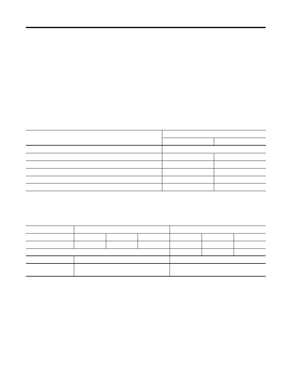
Verifying the Base Unit Loading
1. Enter the SUBTOTAL values from Tables F.1 and F.2. Add the
total current draw for the Base Unit. Verify the values are within
the maximum limits.
2. Using the table below, verify that the MAXIMUM POWER LIMIT
is not exceeded.
Verifying the Expansion Power Supply Loading
Using the values from SUBTOTAL2, verify that the system loading and
I/O distribution are within the limits shown in Table F.5. Consider
future expansion when selecting a power supply.
Table F.3 Base Unit Power Supply Loading - Verify the Current Limits
Current from:
Calculated Current for System
at 5V dc (mA)
at 24V dc (mA)
For 1764-24BWA only, enter sum of any User 24V dc Sensor Current
(E)
MAXIMUM LIMIT
n/a
400 mA User 24V dc
Values from SUBTOTAL1 (Table F.1)
(A1)
(B1)
Values from SUBTOTAL2 (Table F.2)
(A2)
(B2)
TOTAL BASE UNIT CURRENT LOADING
(F)
(G)
MAXIMUM LIMIT
2250 mA at 5V dc
400 mA at 24V dc
Table F.4 Base Unit Power Supply Loading - Verify the Required Power
Catalog Number:
1764-24AWA, 1764-28BXB Base Units
1764-24BWA Base Unit
5V Power Calculation
(F)
x 5V
= W
(F)
x 5V
= W
24V Power Calculation
(G)
x 24V
= W
(G)
x 24V
= W
(E)
x 24V
= W
Add up Total Watts
W
W
MAXIMUM POWER
LIMIT
16W
22W