Analog input module error definition table, Module errors – Rockwell Automation 1790D-NOV2/TNOV2 CompactBlock LDX Analog Modules User Manual
Page 59
Publication 1790-UM001A-EN-P - March 2002
Module Diagnostics and Troubleshooting 5-5
Analog Input Module Error
Definition Table
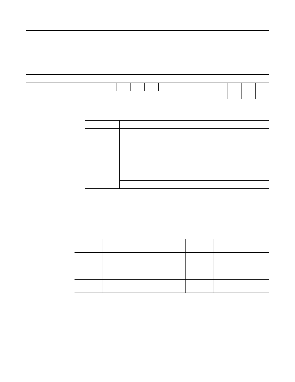
Analog input module errors are expressed on a channel bases in input
read word 4. The structure of the status data is shown below.
Word/Bit Descriptions
Module Errors
Table 5.4 lists possible errors that cause the analog input module
status bits to be set.
Table 5.3
Word
Bit Position
15
14
13
12
11
10
9
8
7
6
5
4
3
2
1
0
4
Not used
S3
S2
S1
S0
Word
Decimal Bit
Description
Read Word 4
Bits 00-03
Status bits for individual channels - Bit 00 corresponds to input
channel 0, bit 01 corresponds to input channel 1 and so on.
When set (1) indicates:
•
No field power
•
Open wire (4-20mA current input only)
•
Under range (4-20mA current input only)
•
Recoverable module fault (whole channel to be set)
•
Unrecoverable module fault (whole channel to be set)
Bits 04-15
Not used: Set to 0
Table 5.4
Status Bit Table 1790D-N4CO/-TN4CO, 1790D-N4VO/-TN4VO
Range
Setting
Underrange
In Range
Overrange
Open
Circuit
Short
Circuit
No Field
Power
4-20mA
<4mA
Set
Not set
>20mA
Not set
Set
Set
Set
0-20mA
<0mA
Not set
Not set
>20mA
Not set
Not set
Not set
Set
0-10V dc
<0V dc
Not set
Not set
>10V
Not set
Not set
Not set
Set