Rockwell Automation 1747-BSN Backup Scanner Module User Manual
Page 14
14
Backup Scanner Module
Publication 1747-5.38
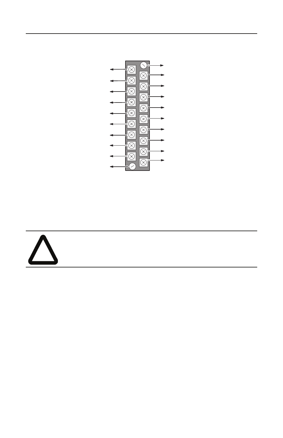
Figure 7
Terminal Pinout
Use Belden™ 9463 cable when wiring the module.
Terminal screws accept a maximum of two #14 AWG (2mm
2
) wires. Tighten
terminal screws only tight enough to immobilize wires. Maximum torque on
terminal screws is 0.9 Nm (8 in-lbs.).
For Remote I/O Installations
1. To ensure a proper earth ground of the cable shield, follow these steps:
2. Strip back enough of the RIO cable to expose enough shield drain wire to
reach a chassis mounting bracket.
3. Attach the ring terminal lug to the end of the shield drain wire.
4. Attach the ring terminal lug to the SLC chassis mounting bracket.
!
ATTENTION: To avoid cracking the terminal block, alternate the removal and
tightening of the slotted release screws. Maximum torque on the release screws
is 0.6 Nm (5.3 in-lbs.).
Important: The RIO cable shield must be grounded at the backup scanner end
only.
Release Screw
HSSL (Line 1 – Blue)
HSSL (Shield)
HSSL (Line 2 – Clear)
Release Screw
DH+ (Line 2) to CPU
DH+ (Shield) to CPU
DH+ (Line 1) to CPU
232 / 485 (COM) to CPU
232 / 485 (B) to CPU
232 / 485 (A) to CPU
LSL (Line 2 – Clear)
LSL (Shield)
LSL (Line 1 – Blue)
232 / 485 (A) to Link
232 / 485 (B) to Link
232 / 485 (COM) to Link
RIO / DH+ (Line 1) to Link
RIO / DH+ (Shield) to Link
RIO / DH+ (Line 2) to Link