Wire the module – Rockwell Automation 1794-IE8H, Series B FLEX I/O 8 Input Hart Analog Module Installation Instructions User Manual
Page 9
FLEX I/O 8 Input HART Analog Module 9
Publication
1794-IN108D-EN-P - January 2014
Wire the Module
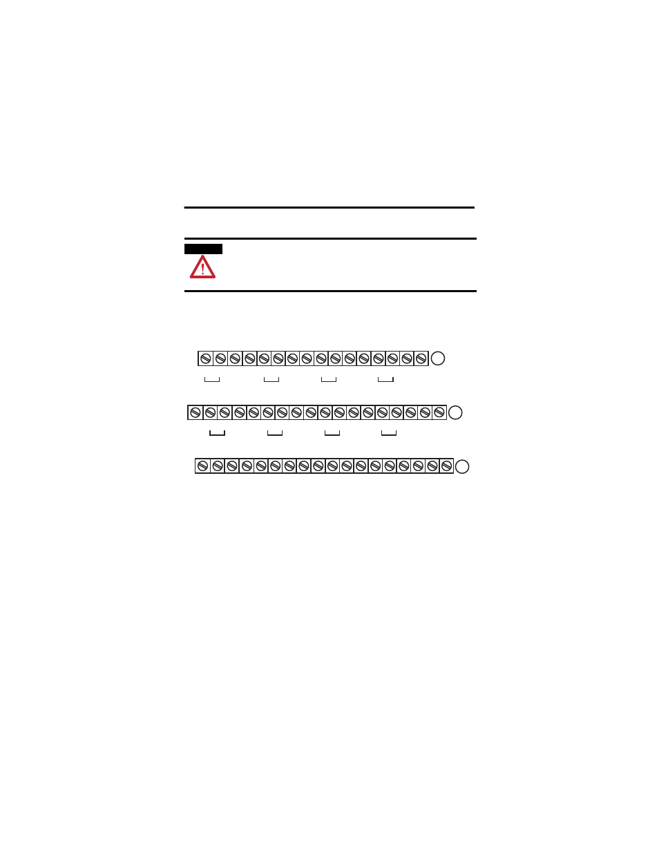
To connect two-wire transmitter devices for 1794-TB3G and 1794-TB3GS
bases, refer to the tables and figure and complete the following.
Module Wiring
1. Connect the individual input wiring to (+) terminals (0, 4, 8, 12) on
the 0 to 15 row (A) and on the 16 to 33 row (B) (terminals 17, 21, 25,
29) as indicated in the table Wire Connections.
2. Connect the associated input to the corresponding (sig) terminal (1, 5,
9, 13) on the 0 to 15 row (A), and on the 16 to 33 row (B) (terminals
18, 22, 26, 30) for each input as indicated in the table Wire
Connections.
WARNING
If you connect or disconnect wiring while the field-side power is on, an
electrical arc can occur. This could cause an explosion in hazardous location
installations. Be sure that power is removed or the area is nonhazardous before
proceeding.
17 18 19 20 21 22 23 24 25 26 27 28 29 30 31 32 33
0 1 2 3 4 5 6 7 8 9 10 11 12 13 14 15
16
35 36 37 38 39 40 41 42 43 44 45 46 47 48 49 50 51
34
(1794-TB3G shown)
+V
COM
A
B
C
NC
+V
COM
NC
+
+
Ch0
Ch1
Ch3
Ch2
sig
sig
+24V DC = Terminals C-34 and C-50
COM
= C-35 and C-51
NC
= No connection
For daisy-chaining : Supply in C-34 (+V) and C-35 (COM)
Supply out C-50 (+V) and C-51 (COM)
24V DC
Supply Out
24V DC
Supply Out
+
Ch4
sig
+
Ch5
sig
+
Ch6
sig
+
Ch7
sig
+
sig
+
sig
44861