Connecting the rs-232 interface module, Connecting the rsć232 interface module – Rockwell Automation 1771-SDN/B INSTL.INSTR.DEVICENET SEMINAR User Manual
Page 18
DeviceNet Seminar Installation Instructions
18
Publication 1787Ć5.5 - December 1995
1203-GK5 Communication Adapter
✓
Both indicators on the 1203-GK5 Communication Adapter
are illuminated green
If not, check the connections to the communication adapter
and the ac drive or SMP-3 overload relay.
SMP-3 Overload Relay
✓
Power Status indicator is illuminated green
1305 AC Drive
✓
Display reads Stopped +0.00Hz
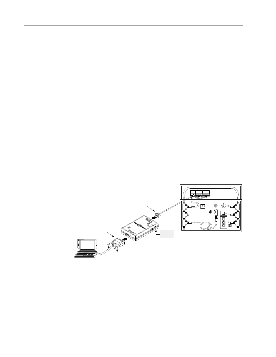
You must have an RS-232 interface module connected and supplied
with power to run the software. Follow the appropriate directions to
power your RS-232 interface module from the network or a 9V dc
power-supply adapter.
Power From Network
1. Set the power switch to 1.
9Ćpin DĆshell
RSĆ232 connector
power
switch
retentive locking screws
5Ćpin unsealed connector
2. Insert the 9-pin D-shell RS-232 connector into the bottom of the
RS-232 interface module.
3. Insert the other 9-pin D-shell RS-232 connector into a serial port
of your computer.
4. Insert the network’s 5-pin unsealed connector into the top of the
RS-232 interface module. This connects the RS-232 interface
module onto the trunk line enabling communication between
devices on the network.
Connecting the
RSĆ232 Interface Module