Rockwell Automation 1794-FLA FlexLogix Controller Installation Instructions User Manual
Page 16
16 FlexLogix Controller System
Publication 1794-IN002G-EN-P - January 2004
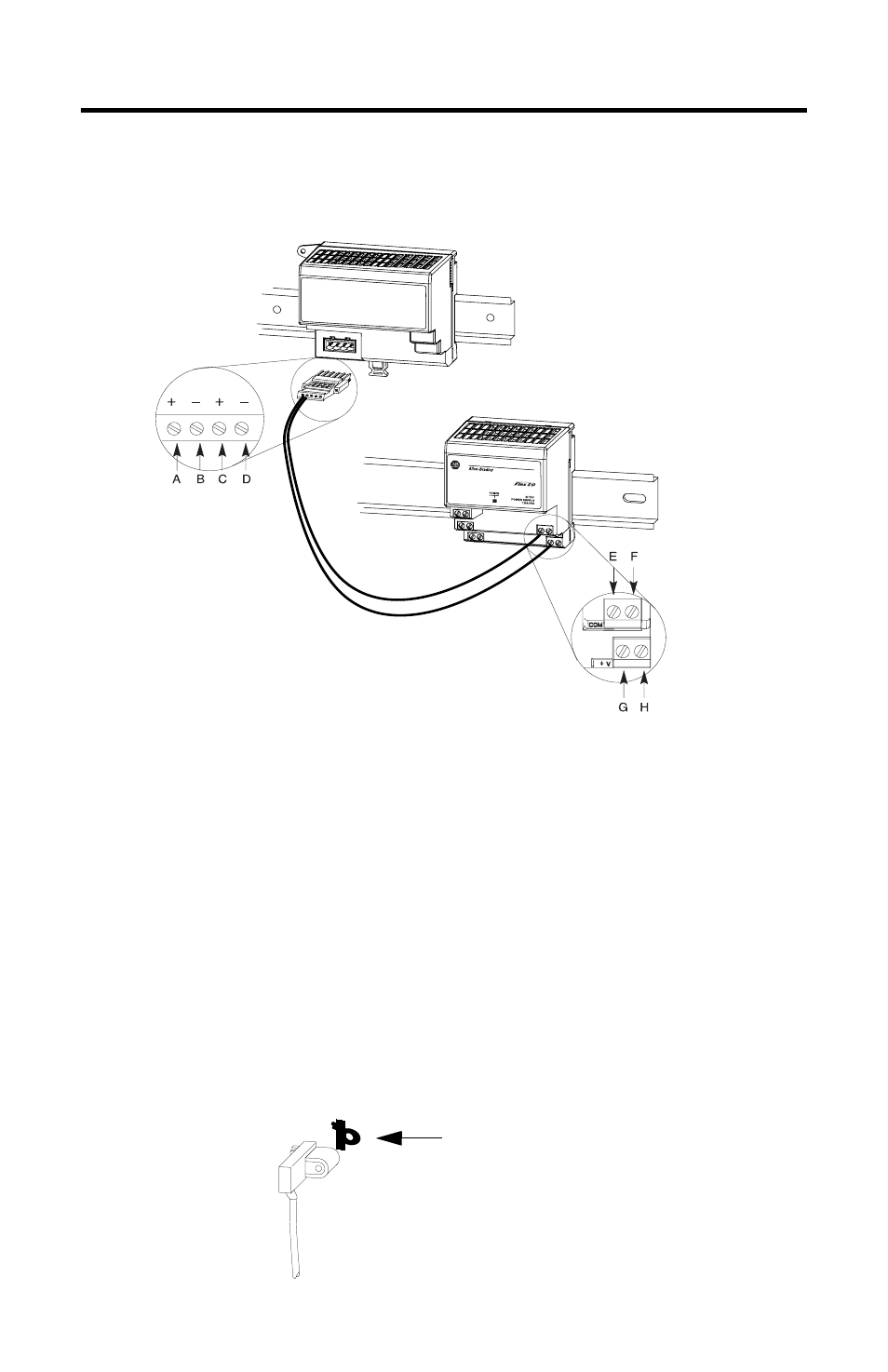
4. Make sure power is not applied to the power supply. Connect the
power supply to the adapter. This diagram and its related instructions
describe a 1794-PS13 power supply.
a. Connect +24V dc input to the left adapter connector, terminal A, to the
bottom, left power connector, terminal G.
b. Connect -24V common to left adapter connector, terminal B, to the top,
left power connector, terminal E.
c. Use connections C and D on the adapter and connection F and H on the
power supply to pass 24V dc power and common to the next module in
the series, if required.
Use the screw-terminal connector plug that comes with the adapter to meet
the requirements for installations in Class I, Division 2 locations.
5. Connect I/O terminal bases and I/O modules to the adapter the same way
you connect them to the controller.
6. Remove the plastic spacer from both ends of the extended-local I/O cable
(1794-CE1 or 1794-CE3).
plastic spacer