Installing the power supply – Rockwell Automation 1771-P3_P4_P5_P5E Power Supply Modules Installation Instructions User Manual
Page 9
Power Supply Modules
9
Publication 1771ĆIN073A-EN-P - March 2002
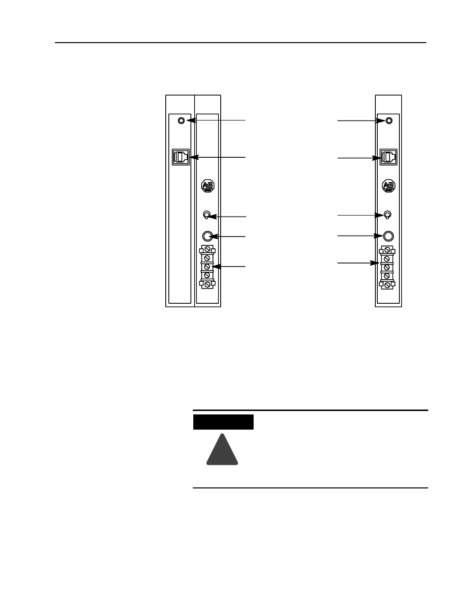
Figure 1
Features of the Power Supply Modules
Status Indicator - Keeps you
informedof module operating
conditions.
P/S Parallel - Makes paralleling
connections between 2 power
supplies easy.
PowerSwitch-Turnsthepower
supply on or off.
Input Fuse - Protects
supply from overload
Terminal Strip - Make input
power connections at this
terminal strip.
P/S
Parallel
24V
DC
+DC
COM
GND
24V dc
POWER
ON
P/S
ACTIVE
5A 32V
NORM BLOW
OFF
12228-I
P/S
Parallel
120V
AC
L1
N
120V ac
POWER
ON
P/S
ACTIVE
1A 125V
SLOW BLOW
OFF
Cat. No. 1771ĆP5 and ĆP5E
Cat. No. 1771ĆP3
GN
D
The power supplies are modular components of the 1771 I/O system.
They must be properly installed in a system chassis. Refer to
publication 1771–IN075 for information on acceptable chassis
installation and proper grounding requirements.
To install the power supply module in the I/O chassis, proceed as
follows:
!
WARNING
If you insert or remove the module while
backplane power is on or attach or remove
wiring to the terminal block, an electrical arc can
occur. This could cause an explosion in
hazardous location installations. Be sure that
power is removed or the area is nonhazardous
before proceeding.
Installing the Power
Supply