Rockwell Automation 1791-XXXX Discrete I/O AC and DC Block I/O Input and Output Modules User Manual
Page 59
SW1
SW2
Open cover to
access switches
1
30
1791Ć16B0
24V dc INPUT
INPUT INPUT
00
01
02
03
04
05
06
07
10
11
12
13
14
15
16
17
12403-I
8
7
6
5
4
3
2
1
0
1
8
7
6
5
4
3
2
1
0
1
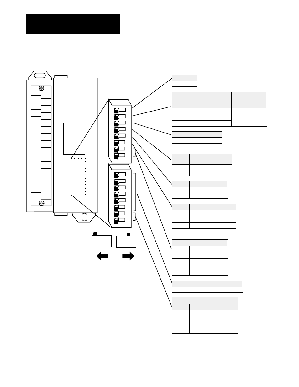
Position = 1
Position = 0
End View
NOTE:
Default Switch
Settings = 0
Set switch SW2-3 to 0 if this rack will have a unique
address (not complemented). If this rack address is a
duplicate of another I/O block or chassis, set the switch to
1 for primary or 0 for complementary. Refer to Table
4.G
for the complementary I/O rack address.
Only block I/O modules with all inputs or all
outputs can use complementary I/O.
Series A block I/O modules do not support
complementary I/O. If using series A modules, set
this switch to 0.
ATTENTION: Cycle power to the module after setting the switches.
Configuring Your Block I/O for PLC
Family Programmable Controllers
Chapter 4
4-2
Figure 4.1
Switch Settings for the ac and dc Block I/O Modules (16Ćpoint illustrated)
SW2-8
Not used
Not used
dc Applications
ac Applications
SW2-7
Filter Speed Select
SW2-7
0
Slow
1
Fast
Not Used
Note: For inputs only
SW2-6
Last I/O Group
0
Not last rack
1
Last rack
SW2-5
Processor
Restart/Lockout (PRL)
0
Processor Restart
1
Processor Lockout
SW2-4
Hold Last State
0
Reset Outputs
1
Hold Last State
SW2-3
Complementary I/O
1
0
NonĆCompleted Systems
0
Complementary Rack
1
1
Primary Rack
1
1
See Note.
Communication Rate
SW2-2 SW2-1
Bits/s
0
0
57.6 K
0
1
115.2 K
1
0
230.4 K
1
1
230.4 K
SW1-3 thru 8
Rack Address
Refer to Table 4.F for settings.
Starting Quarter
SW1-2 SW1-1
Module Group
0
0
0 (1st)
0
1
2 (2nd)
1
0
4 (3rd)
1
1
6 (4th)