Rockwell Automation 1791-XXXX Discrete I/O AC and DC Block I/O Input and Output Modules User Manual
Page 48
Installing Block I/O
Chapter 3
3-29
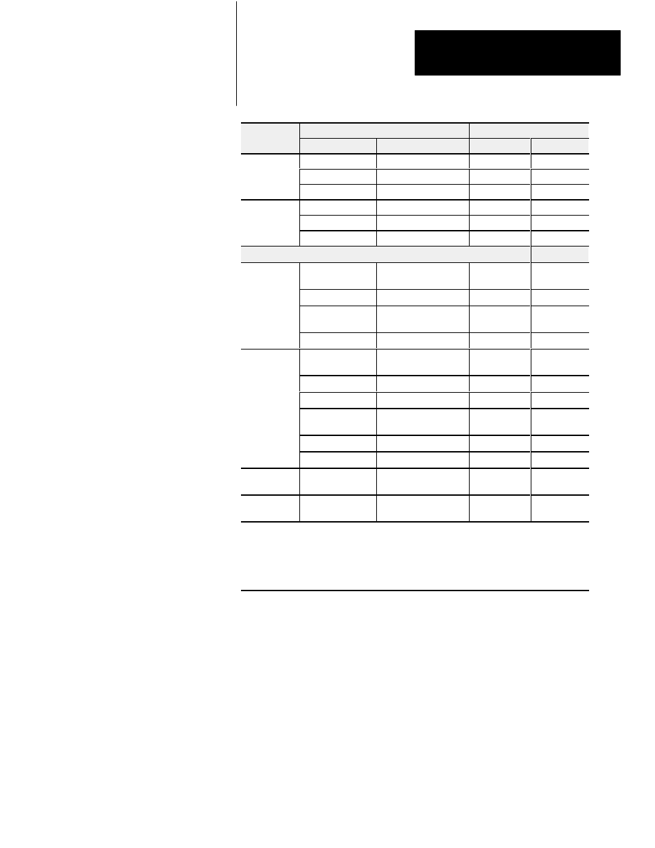
Connections
1791-16BC Series B
Connector/Terminal
Connections
Designation
Description
Left
Right
P
+24
+24V dc Power
1
Power
Connections
RET +24
dc Return
3
Connections
GND
Chassis ground
2
1
R
t I/O
BLU
Blue wire - RIO
6
Remote I/O
Connections
CLR
Clear wire - RIO
8
Connections
SHD
Shield - RIO
7
I/O Connections
PLC: in 00 thru 07
SLC: in 00 thru 07
PLC: Input 00 thru 07
SLC: Input 00 thru 07
16, 18, 20, 22,
24, 26, 28, 30
Input
RET 1
dc input return
12, 14
2
Input
(G)
6
PLC: in 10 thru 17
SLC: in 08 thru 15
PLC: Input 10 thru 17
SLC: Input 08 thru 15
15, 17, 19, 21,
23, 25, 27, 29
RET 2
dc input return
11, 13
3
PLC: out 00 thru 07
SLC: out 00 thru 07
PLC: Output 00 thru 07
SLC: Output 00 thru 07
15, 13, 11, 9,
7, 5, 3, 1
Vdc 3
+24V dc output supply
19, 17
4
Output
RET 3
dc output return
21
Output
(G)
7
PLC: out 10 thru 17
SLC: out 08 thru 15
PLC: Output 10 thru 17
SLC: Output 08 thru 15
16, 14, 12,
10, 8, 6, 4, 2
Vdc 4
+24V dc output supply
20, 18
5
RET 4
dc output return
22
Not used
For internal test only;
not for customer use.
4, 5, 9, 10
29, 27, 26
No Conn
No internal connection;
customer can use.
30, 28, 25,
24, 23
1 Connect chassis ground to equipment grounding stud. These are not internally connected.
2 Terminals 12 and 14 are internally connected.
3 Terminals 11 and 13 are internally connected.
4 Terminals 17 and 19 must be externally connected by customer to accommodate amperage rating.
5 Terminals 20 and 18 must be externally connected by customer to accommodate amperage rating.
6
IN (G) = input module group.
7
OUT (G) = output module group.