Installing block i/o chapter 3, Series b – Rockwell Automation 1791-XXXX Discrete I/O AC and DC Block I/O Input and Output Modules User Manual
Page 39
Installing Block I/O
Chapter 3
3-20
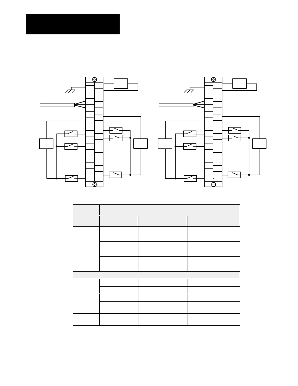
Figure 3.14
Input Wiring Connections for the 1791Ć16B0
Series B
RIO
1
30
PLC
24V dc
24V dc
24V dc
+
Ć
+
Ć
+
Ć
NOTE: Ret 1 connections are internally connected together.
Ret 2 connections are internally connected together.
+24
GND
BLU
CLR
in 00
in 01
in 02
in 03
in 04
in 05
in 06
in 07
RET
1
RET
1
NOT
USED
RET
+24
SHD
RET
2
in 10
in 12
in 13
in 14
in 15
in 16
in 17
RET
2
NOT
USED
NOT
USED
NOT
USED
in 11
RIO
1
30
SLC
24V dc
24V dc
24V dc
+
Ć
+
Ć
+
Ć
+24
GND
BLU
CLR
in 00
in 01
in 02
in 03
in 04
in 05
in 06
in 07
RET
1
RET
1
NOT
USED
RET
+24
SHD
RET
2
in 08
in 10
in 11
in 12
in 13
in 14
in 15
RET
2
NOT
USED
NOT
USED
NOT
USED
in 09
1
2
1
2
Connections
1791Ć16B0
Series B
Connections
Designation
Description
Terminal No.
P
+24
+24V dc Power
1
Power
Connections
RET +24
dc Return
3
Connections
GND
Chassis ground
2
1
R
t I/O
BLU
Blue wire Ć RIO
6
Remote I/O
Connections
CLR
Clear wire Ć RIO
8
Connections
SHD
Shield Ć RIO
7
I/O Connections
Input
in 00 thru in 07
Input 00 thru 07
16, 18, 20, 22, 24, 26, 28, 30
Input
RET 1
RET 1 Input Common
12, 14
2
RET 2
RET 2 Input Common
11, 13
3
Input
PLC: in 10 thru in 17
SLC: in 08 thru in 15
PLC: Input 10 thru input 17
SLC: Input 08 thru input 15
15, 17, 19, 21, 23, 25, 27, 29
Not Used
For internal test only; not for
customer use.
4, 5, 9, 10
1 Connect chassis ground to equipment grounding stud. These are not internally connected.
2 Terminals 12 and 14 are internally connected.
3 Terminals 11 and 13 are internally connected.