Installing block i/o chapter 3, Series b – Rockwell Automation 1791-XXXX Discrete I/O AC and DC Block I/O Input and Output Modules User Manual
Page 26
Installing Block I/O
Chapter 3
3-7
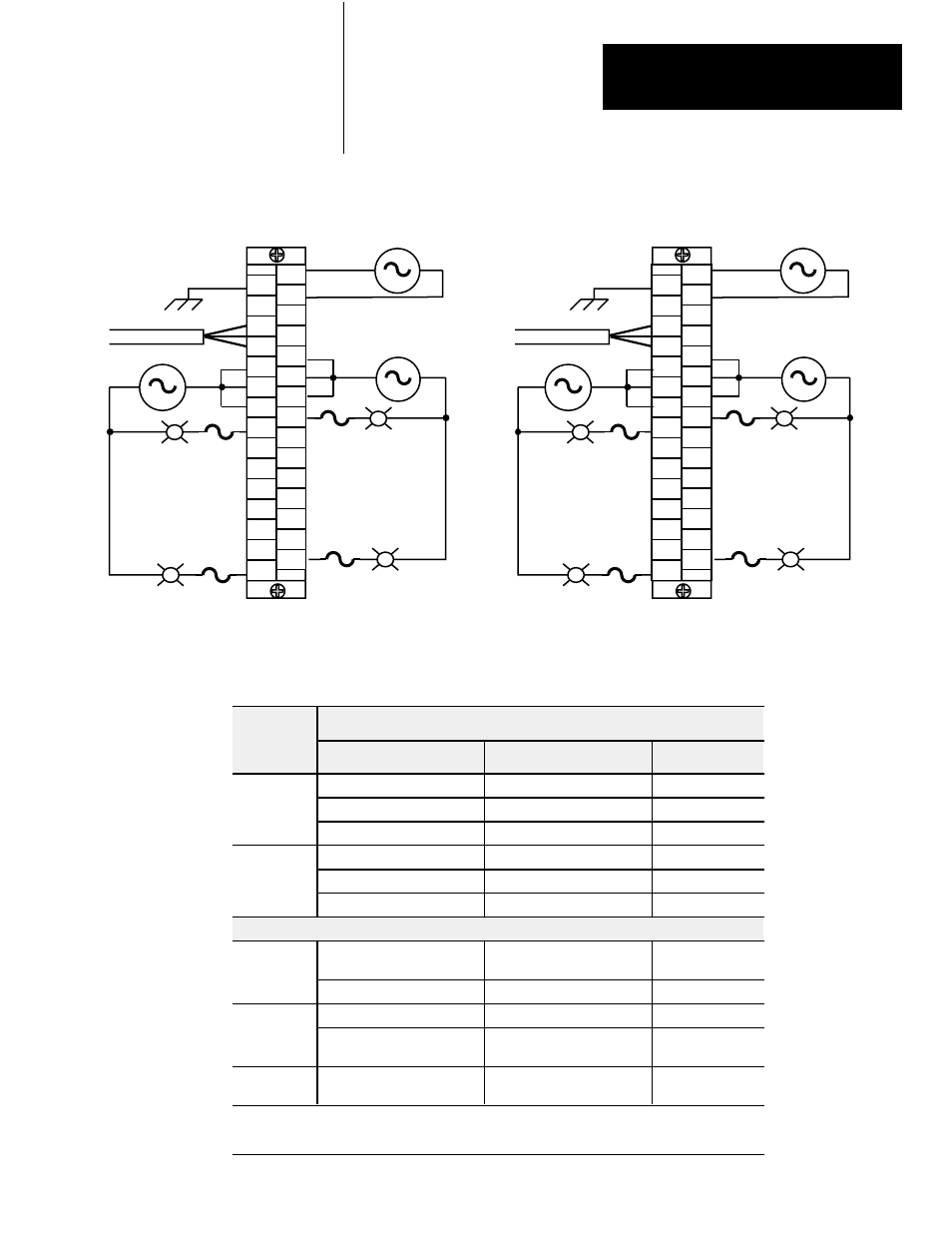
Figure 3.6
Output Wiring Connections for the 1791Ć0A16
Series B
RIO
L2/N
L1
L2/N L1
1
30
SLC
L2/N
L1
L1
GND
N
NOT
USED NOT
USED
BLU
SHD
out 00
out 01
out 02
out 03
out 04
out 05
out 06
out 07
out 08
out 10
out 11
out 12
out 13
out 14
out 09
out 15
CLR
COM
1
COM
2
COM
2
NOT
USED
COM
2
L1
GND
BLU
SHD
out 02
out 03
out 04
out 05
out 06
out 08
out 10
out 11
out 12
out 13
out 14
out 09
out 15
COM
1
COM
1
out 00
out 01
CLR
NOT
USED
N
out 07
RIO
L2/N
L1
L2/N L1
1
30
PLC
L2/N
L1
L1
GND
N
NOT
USED NOT
USED
BLU
SHD
out 00
out 01
out 02
out 03
out 04
out 05
out 06
out 07
out 10
out 12
out 13
out 14
out 15
out 16
out 11
out 17
CLR
L1Ć1 connections must be externally connected together to accommodate total amperage.
L1Ć2 connections must be externally connected together to accommodate total amperage.
Output fusing is recommended. Refer to Table 2.B on page 2Ć8.
NOTE:
L1-1
L1-1
L1-1
L1-2
L1-2
L1-2
L1-1
L1-1
L1-1
L1-2
L1-2
L1-2
1
2
1
2
29
30
29
30
Connections
1791Ć0A16
Series B
Connections
Designation
Description
Terminal
Power
L1
ac hot
1
Power
Connections
N
ac neutral
3
GND
Chassis ground
2
1
Remote I/O
BLU
Blue wire Ć RIO
6
Remote I/O
Connections
CLR
Clear wire Ć RIO
8
SHD
Shield Ć RIO
7
I/O Connections
Output
out 00 thru out 07
Output 00 thru 07
16, 18, 20, 22, 24,
26, 28, 30
Output
L1-1
L1 output supply
10, 12, 14
2
L1-2
L1 output supply
9, 11, 13
3
Output
PLC: out 10 thru out 17
SLC: out 08 thru out 15
PLC: Output 10 thru 17
SLC: Output 08 thru 15
15, 17, 19, 21, 23,
25, 27, 29
Not used
For internal test only; not for
customer use.
4, 5
1 Connect chassis ground to equipment grounding stud. These are not internally connected.
2 Terminals 10, 12 and 14 must be externally connected by customer.
3 Terminals 9, 11 and 13 must be externally connected by customer.