Rockwell Automation 1771-A1B_A2B_A3B_A3B1_A4B SERIES B Universal I/O Chassis Installation Instructions User Manual
Page 7
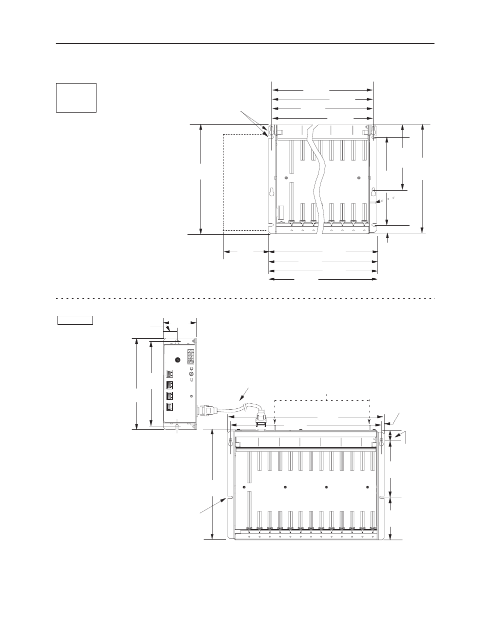
Universal I/O Chassis
7
Publication 1771ĆIN075A-EN-P - March 2002
I/O Chassis with External Power SupplyMounting Dimensions
315mm
(12.41")
610mm
(24.01")
16-slot 1771-A4B
12-slot 1771-A3B1
356mm
(14.01")
229mm
(9.
01")
8-slot 1771-A2B
4-slot 1771-A1B
12-slot
8-slot
4-slot
16-slot
1771ĆA1B
1771ĆA2B
1771ĆA3B1
1771ĆA4B
1771ĆP1
1771ĆP2
1771ĆP7
1771ĆPS7
Power
Supply
12451ĆI
91mm
(3.6")
You can mount 1771ĆP1, ĆP2, ĆP7 and ĆPS7
power supplies on the left side plate of the
I/O chassis, or up to 5 cableĆfeet from the I/O chassis.
483mm
(19.01")
593mm
(23.32") 466mm
(18.32")
339mm
(13.32")
212mm
(8.32")
254mm
(10")
grounding
stud
178mm
(7.00")
307mm
(12.09")
25.4mm
(1.0")
use four 1/4Ć20 (M6 x 10)
mounting bolts to secure, using
slots, keyholes, or a
combination of both
Clearance depth is 221mm (8.7")
293mm
(11.53")
315mm
(12.41")
115mm
(4.53")
Depth is 183mm (7.2")
A 1771ĆPS7 power supply cannot be mounted on the side
of the 1771ĆA3B I/O chassis. See the installation data for
the 1771ĆPS7 power supply for more information on
mounting the supply to the I/O chassis.
1 cable-foot
1
46mm
(1.8")
339mm
(13.35")
465mm
(18.31")
483mm
(19.01")
9mm
(0.34")
26mm
(1.02")
178mm
(7.01")
130mm
(5.10")
1771ĆA3B
grounding studs
use 1/4Ć20 (M6 x 10)
mounting bolts (four places)
- 20P PowerFlex DC Drive - Frame D Bimetal Thermostat (10 pages)
- 1336S_F_T_E_R F Frame Snubber Resistor Repl. (6 pages)
- 22-COMM PowerFlex 4-Class DSI (Drive Serial Interface) Network Communication Adapter (4 pages)
- 8-545 Plug In Solid State Relay (2 pages)
- 20-HIM-B1 PowerFlex 7-Class HIM Bezel (DPI) (4 pages)
- 100 Contactors with DC Coil (1 page)
- 100 Contactors with DC Coil (2 pages)
- 20P PowerFlex DC Drive - Frame D Switching Power Supply Circuit Board (6 pages)
- 140G-MTFx_MTHx_MTIx_MTKx Trip Unit Installation-140G-M (6 pages)
- 45BRD Analog Laser Sensor (4 pages)
- 20D Multi-Device Interface Option Board for PowerFlex 700S Drives (20 pages)
- 56RF RFID 18 mm Cylindrical Transceiver (2 pages)
- 42KC Miniature Rectangular: 5V DC Version (2 pages)
- 20P PowerFlex DC Drive - Frame A Switching Power Supply Circuit Board (16 pages)
- 21P-MISC-A-TP-2 Transition Tube Kit #C19-6/7 For PowerFlex 755 w/OEM Liquid Cooling Fr 6/7 Drive (2 pages)
- 42BT Background Suppression Sensor (3 pages)
- 42CB High Speed 18mm Cylindrical (4 pages)
- 140EX-JE2_JE3 Molded Case Circuit Breaker (4 pages)
- 140G-K-EAM1A Early Make Aux Contact for Rotary Handle Oper Mech-140G-K (1 page)
- 140G-K-EAM1A Early Make Aux Contact for Rotary Handle Oper Mech-140G-K (3 pages)
- 20-HIM-A6 PowerFlex (Human Interface Module) (74 pages)
- 42CF General Purpose 12mm Cylindrical (4 pages)
- 20D PowerFlex 700S Phase II Drive Frames 1...6 (80 pages)
- 140EX-HE1_HE2 Molded Case Circuit Breaker (6 pages)
- 140EX-HE1_HE2 Molded Case Circuit Breaker (4 pages)
- 20B PowerFlex 700 Custom Firmware - Pump Off (12 pages)
- 20-WIM-N4S DPI Wireless Interface Module (92 pages)
- 140U H-Frame Circuit Breaker Fixed and Adjustable Thermal Trip (7 pages)
- 140U H-Frame Circuit Breaker Fixed and Adjustable Thermal Trip (2 pages)
- 60-2619, 42JS Swivel/Tilt Mounting Bracket (1 page)
- 22A PowerFlex 4/40/400 Flange Mount (4 pages)
- 45MLA Controller Installation Instructions (16 pages)
- 20P PowerFlex DC Drive - Cooling Fan for Frame A Drives Above 73A at 230V 460V AC (6 pages)
- 42JS Series 7000 to 42JS VisiSight Replacement Kit (2 pages)
- 22A PowerFlex 4-Class HIM Bezel (DSI) (4 pages)
- 42CS Stainless Steel Photoelectric Sensors (4 pages)
- 20L-LL PowerFlex 700L Liquid-to-Liquid Heat Exchanger (40 pages)
- 20P PowerFlex DC Drive - Frame B SCR Modules (20 pages)
- 22B PowerFlex 40 Quick Start FRN 5.xx - 6.xx (161 pages)
- 22B PowerFlex 40 Quick Start FRN 5.xx - 6.xx (22 pages)
- 22F PowerFlex 4M Input RFI Filters (2 pages)
- 45LFM Capacitive Label Sensor (4 pages)
- 140G-Rx Installation Instruction-140G-R (2 pages)
- 140G-Rx Installation Instruction-140G-R (29 pages)
- 22C PowerFlex 400 AC Drive Quick Start - FRN 1-4.xx (28 pages)