Rockwell Automation 1771-A1B_A2B_A3B_A3B1_A4B SERIES B Universal I/O Chassis Installation Instructions User Manual
Page 17
Universal I/O Chassis
17
Publication 1771ĆIN075A-EN-P - March 2002
IMPORTANT
Firmly press the module into the chassis
backplane connector. The chassis locking bar
will not close if any modules are not seated
properly.
Repeat for each module you install.
3. Swing the chassis locking bar down into place to secure the
modules. Make sure the locking pins engage.
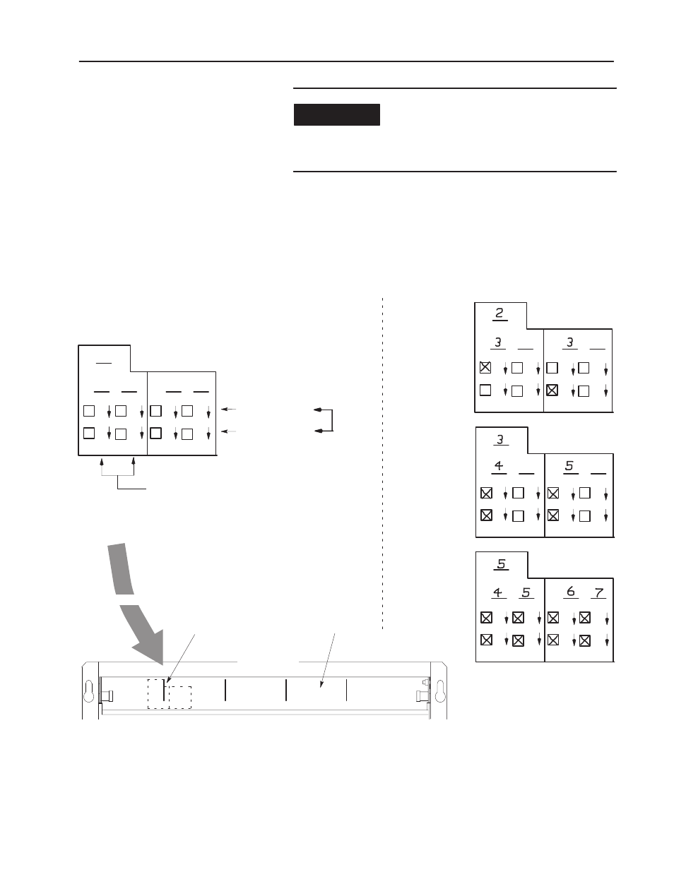
4. Apply the I/O group labels over the scored lines on the I/O
chassis locking bar as shown below. On each label, record the
I/O rack number, I/O group number and terminal numbering for
each module.
R
G
G
G
G
R
G
G
G
G
R
G
G
G
G
Examples:
2-slot addressing
(8Ćpoint I/O modules)
1-slot addressing
(16Ćpoint I/O modules)
1/2-slot addressing
(32Ćpoint I/O modules)
R
G
G
00
07
10
17
10
17
10
17
10
17
G
G
A digital 32Ćpoint I/O module
in any slot has its terminals
numbered for two I/O groups.
A digital 8Ćpoint
I/O module has its
terminals numbered:
A digital 16Ćpoint
I/O module has its
terminals numbered:
00-07 (left slot)
or
10-17 (right slot)
00-07
10-17
and
1st I/O group - 00-07 and 10-17
2nd I/O group - 00-07 and 10-17
12448ĆI
locking bar
scored line
front of chassis
placement
I/O Group Label
00
07
00
07
00
07
10
17
00
07
10
17
00
07
10
17
00
07
10
17
00
07
10
17
00
07
10
17
00
07
10
17
00
07
10
17
00
07
10
17
00
07
10
17
00
07
10
17
00
07
10
17
00
07
5. Use your module’s installation data to make other wiring
connections.
6. Apply power to the system and run tests as required.