Connect equipment grounding conductor – Rockwell Automation 1771-A1B_A2B_A3B_A3B1_A4B SERIES B Universal I/O Chassis Installation Instructions User Manual
Page 11
Universal I/O Chassis
11
Publication 1771ĆIN075A-EN-P - March 2002
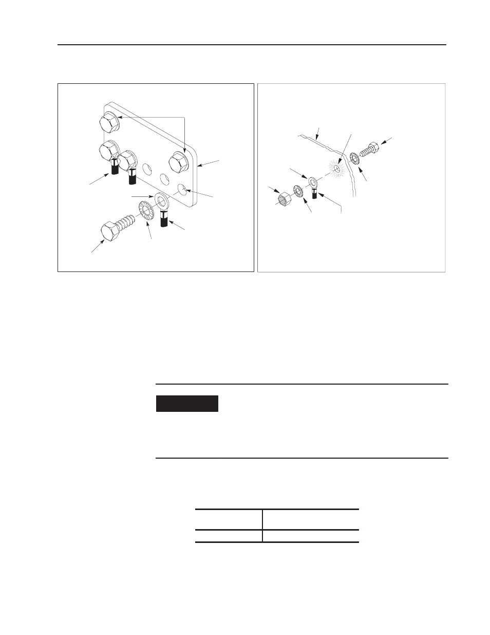
Connect Equipment Grounding Conductor
equipment
grounding
conductors
ground
lug
bolt
star
washer
Grounding electrode
conductor to grounding
electrode system
tapped hole
ground bus
ground bus
mounting
13271
Connecting Equipment Ground Conductor to a Ground Bus
10020
Connecting Equipment Ground Connector to an Enclosure Wall
Enclosure
Wall
Equipment-Grounding
Conductor
Scrape
Paint
Star
Washer
Nut
Ground
Lug
Scrape paint on enclosure wall
and use a star washer.
Bolt
Functional Ground
•
use 2.54cm (1in.) copper braid or 10.0mm
2
(8 AWG) copper wire to connect
each chassis, the enclosure and a central ground bus mounted on the
backĆpanel
•
use a steel enclosure to guard against electromagnetic interference (EMI)
•
make sure the enclosure door viewing window is a laminated screen or a
conductive optical substrate (to block EMI)
Protective Earth Ground
•
use a2.5mm
2
(14 AWG) copper wire for the equipment grounding conductors
•
install a bonding wire [2.5mm
2
(14AWG) minimum] for electrical contact
between the door and the enclosure; do not rely on the hinge
IMPORTANT
Do not lay one ground lug directly on top of the other; this
type of connection can become loose due to compression
of the metal lugs.
Place the first lug between a star washer and a nut with a
captive star washer.
After tightening the nut, place the second lug between the
first nut and a second nut with a captive star washer.
Connect an equipment grounding conductor directly from each
chassis to an individual bolt on the ground bus.
For chassis with
Connect the equipment
grounding conductor using
aground stud
the grounding stud