Install your i/o modules – Rockwell Automation 1771-A1B_A2B_A3B_A3B1_A4B SERIES B Universal I/O Chassis Installation Instructions User Manual
Page 16
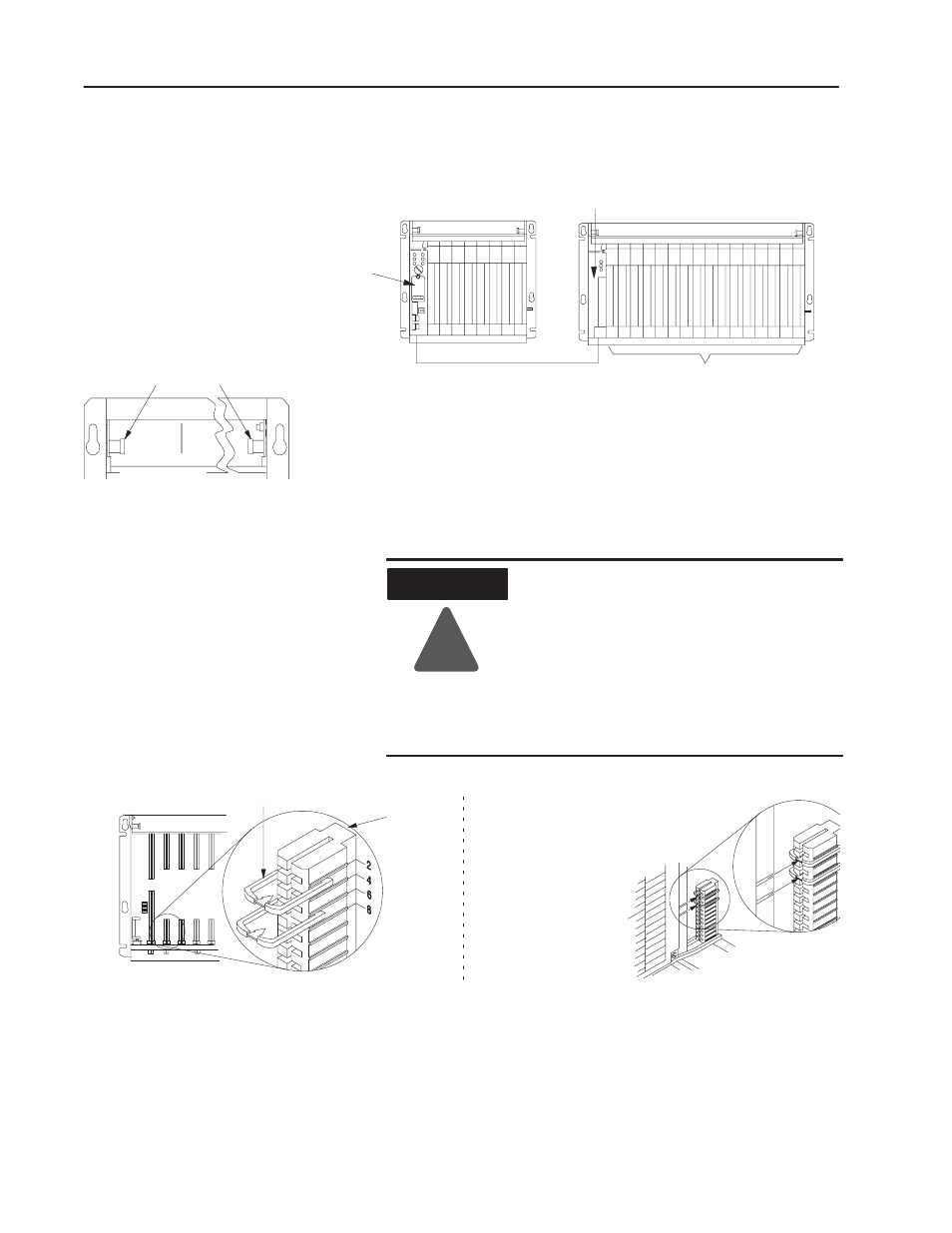
front of chassis
lockingĆbar pins
12453ĆI
Universal I/O Chassis
16
Publication 1771ĆIN075A-EN-P - March 2002
The left-most slot of each chassis accepts either a processor module or
an I/O adapter module. The other slots in the chassis accept
communication modules, I/0 modules and power-supply modules.
PLCĆ5 processor
communication cable
I/O modules
I/O adapter module
11865
1771ĆA2B I/O chassis
1771ĆA4B I/O chassis
To insert a module:
1. Pull the locking-bar pins to release the locking bar and swing it
up.
2. Use the installation data/user manual for your module to:
a.
position the keying bands in the backplane connectors to
correspond to the key slots on the module. This prevents
you from inserting the wrong module in this slot.
ATTENTION
!
Observe the following precautions when
inserting or removing keys:
D insert or remove keys with your fingers
D make sure that key placement is correct
Incorrect keying or the use of a tool can result
in damage to the backplane connector and
possible system faults.
Each I/O module is slotted in two places
at the rear edge of the circuit board.
These slots are intended to mate with the
plastic keys supplied with each chassis.
keyingbands
I/O chassis
I/O module
I/O chassis
backplane connector
backplane
connector
b.
install the module.
Install Your I/O Modules