I/o chassis mounting dimensions – Rockwell Automation 1771-A1B_A2B_A3B_A3B1_A4B SERIES B Universal I/O Chassis Installation Instructions User Manual
Page 6
Universal I/O Chassis
6
Publication 1771ĆIN075A-EN-P - March 2002
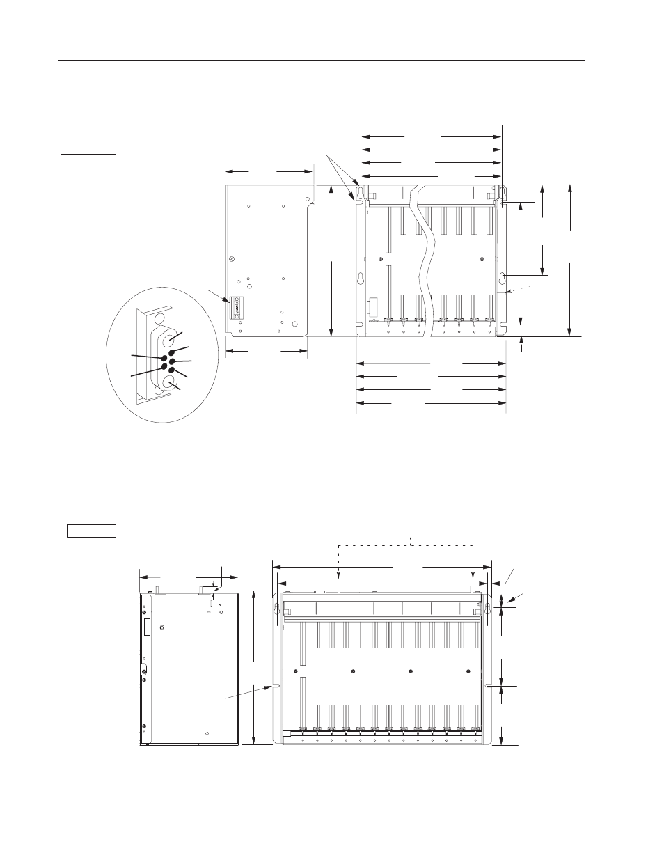
I/O Chassis Mounting Dimensions
315mm
(12.41")
16-slot 1771-A4B
12-slot 1771-A3B1
8-slot 1771-A2B
4-slot 1771-A1B
254mm
(10")
12-slot
8-slot
4-slot
16-slot
1771ĆA1B
1771ĆA2B
1771ĆA3B1
1771ĆA4B
193mm
1
(7.60")
593mm
(23.32") 466mm
(18.32")
339mm
(13.32")
212mm
(8.32")
171mm
(6.75")
610mm
(24.01")
483mm
(19.01") 356mm
(14.01")
229mm
(9.01")
power connector
grounding
stud
use four 1/4Ć20 (M6 x 10)
mounting bolts to secure, using
slots, keyholes, or a
combination of both
A1
3
4
5
A2
1
2
A1 backplane common
A2 backplane +5V dc
1
no connection
2
backplane processor enable
3
backplane +5V dc sense
4
backplane signal groundsense
5
no connection
13445
178mm
(7.00")
307mm
(12.09")
25.4mm
(1.0")
use 1/4Ć20 (M6 x 10)
mounting bolts (four
places)
12450ĆI
217mm
1
(8.54")
339mm
(13.35")
465mm
(18.31")
483mm
(19.01")
9mm
(0.34")
26mm
(1.02")
178mm
(7")
130mm
(5.10")
1
Total maximum depth dimension per installation depends on module
wiring andconnectors.
1771ĆA3B
18mm
(0.71")
grounding studs
- 20P PowerFlex DC Drive - Frame D Bimetal Thermostat (10 pages)
- 1336S_F_T_E_R F Frame Snubber Resistor Repl. (6 pages)
- 22-COMM PowerFlex 4-Class DSI (Drive Serial Interface) Network Communication Adapter (4 pages)
- 8-545 Plug In Solid State Relay (2 pages)
- 20-HIM-B1 PowerFlex 7-Class HIM Bezel (DPI) (4 pages)
- 100 Contactors with DC Coil (1 page)
- 100 Contactors with DC Coil (2 pages)
- 20P PowerFlex DC Drive - Frame D Switching Power Supply Circuit Board (6 pages)
- 140G-MTFx_MTHx_MTIx_MTKx Trip Unit Installation-140G-M (6 pages)
- 45BRD Analog Laser Sensor (4 pages)
- 20D Multi-Device Interface Option Board for PowerFlex 700S Drives (20 pages)
- 56RF RFID 18 mm Cylindrical Transceiver (2 pages)
- 42KC Miniature Rectangular: 5V DC Version (2 pages)
- 20P PowerFlex DC Drive - Frame A Switching Power Supply Circuit Board (16 pages)
- 21P-MISC-A-TP-2 Transition Tube Kit #C19-6/7 For PowerFlex 755 w/OEM Liquid Cooling Fr 6/7 Drive (2 pages)
- 42BT Background Suppression Sensor (3 pages)
- 42CB High Speed 18mm Cylindrical (4 pages)
- 140EX-JE2_JE3 Molded Case Circuit Breaker (4 pages)
- 140G-K-EAM1A Early Make Aux Contact for Rotary Handle Oper Mech-140G-K (1 page)
- 140G-K-EAM1A Early Make Aux Contact for Rotary Handle Oper Mech-140G-K (3 pages)
- 20-HIM-A6 PowerFlex (Human Interface Module) (74 pages)
- 42CF General Purpose 12mm Cylindrical (4 pages)
- 20D PowerFlex 700S Phase II Drive Frames 1...6 (80 pages)
- 140EX-HE1_HE2 Molded Case Circuit Breaker (6 pages)
- 140EX-HE1_HE2 Molded Case Circuit Breaker (4 pages)
- 20B PowerFlex 700 Custom Firmware - Pump Off (12 pages)
- 20-WIM-N4S DPI Wireless Interface Module (92 pages)
- 140U H-Frame Circuit Breaker Fixed and Adjustable Thermal Trip (7 pages)
- 140U H-Frame Circuit Breaker Fixed and Adjustable Thermal Trip (2 pages)
- 60-2619, 42JS Swivel/Tilt Mounting Bracket (1 page)
- 22A PowerFlex 4/40/400 Flange Mount (4 pages)
- 45MLA Controller Installation Instructions (16 pages)
- 20P PowerFlex DC Drive - Cooling Fan for Frame A Drives Above 73A at 230V 460V AC (6 pages)
- 42JS Series 7000 to 42JS VisiSight Replacement Kit (2 pages)
- 22A PowerFlex 4-Class HIM Bezel (DSI) (4 pages)
- 42CS Stainless Steel Photoelectric Sensors (4 pages)
- 20L-LL PowerFlex 700L Liquid-to-Liquid Heat Exchanger (40 pages)
- 20P PowerFlex DC Drive - Frame B SCR Modules (20 pages)
- 22B PowerFlex 40 Quick Start FRN 5.xx - 6.xx (161 pages)
- 22B PowerFlex 40 Quick Start FRN 5.xx - 6.xx (22 pages)
- 22F PowerFlex 4M Input RFI Filters (2 pages)
- 45LFM Capacitive Label Sensor (4 pages)
- 140G-Rx Installation Instruction-140G-R (2 pages)
- 140G-Rx Installation Instruction-140G-R (29 pages)
- 22C PowerFlex 400 AC Drive Quick Start - FRN 1-4.xx (28 pages)