Configure the module – Rockwell Automation 1771-IR Installation Instructions User Manual
Page 7
RTD Input Module
7
Publication 1771Ć5.63 - November 1998
Use the configuration information below to configure your module
to your specifications.
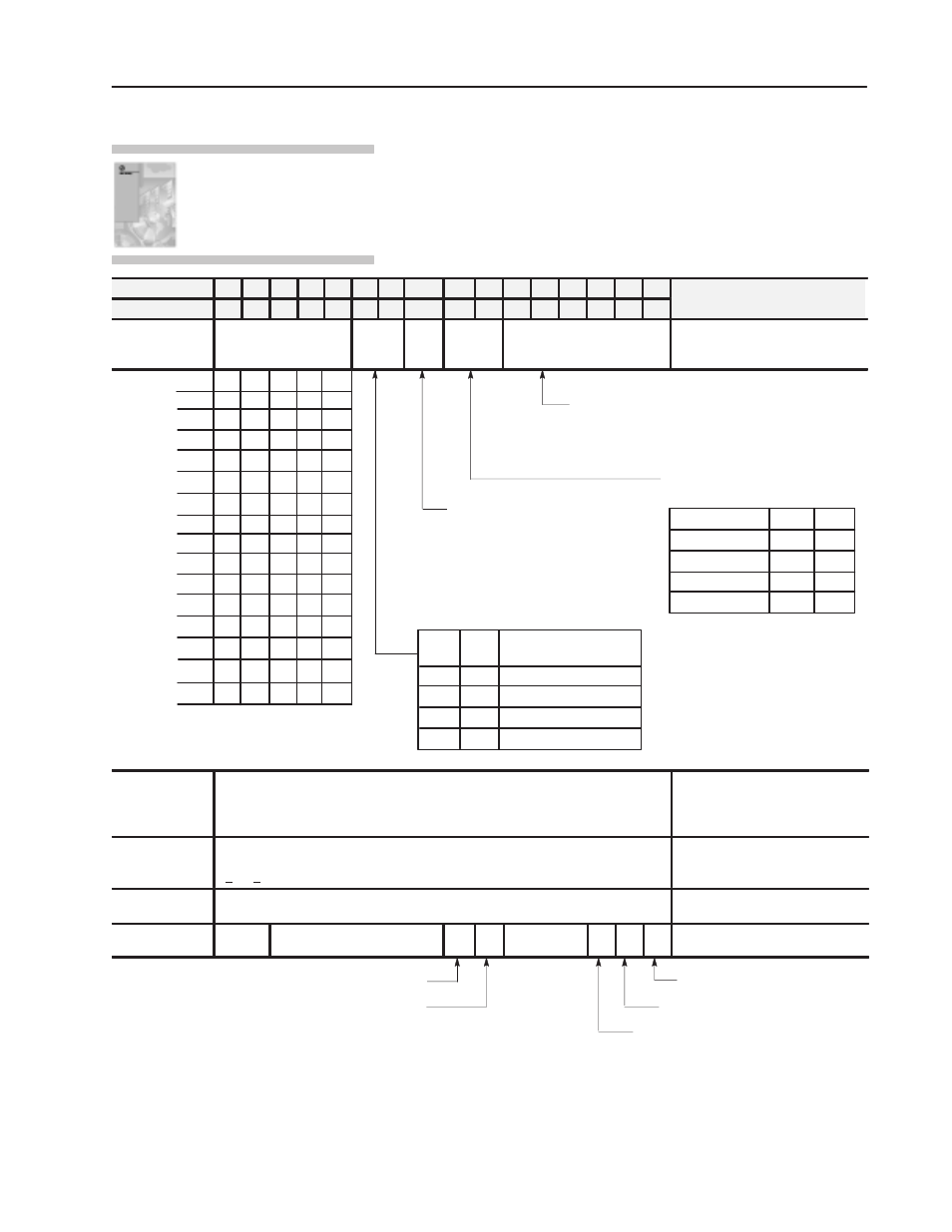
Dec. Bits
15 14 13 12 11 10 09
08
07 06 05 04 03 02 01 00
Description
Octal Bits
17 16 15 14 13 12 11
10
07 06 05 04 03 02 01 00
Description
Word 1
Real Time Sampling Ć
default = no RTS
Data
Format
RTD
Type
Units of
Measure
Single channel in ohms
Real time sampling, data format,
RTD type units of measure, and
single channel in ohms
3.1s
Intemperature mode:
0 = Entire module is platinum
1 = Entire module is 10 ohm copper.
Enter exact value in word 2.
Inohms mode:
0 = 30mohm/count resolution
1 = 10mohm/count resolution
If any of these bits are set, the corresponding input
channel will be reported in ohms. If RTDs other than 10
ohm copper or 100 ohm platinum are used you must
report those channels in ohms, not degrees. Data format
on a channel displayed in ohms will default to binary.
Determines what units of measure
the module reports.
Units of measure Bit 07 Bit 06
Degrees C
Degrees F
Ohms
Not used
0
0
0
1
1
0
1
1
Set to match your
processor.
BCD (default)
Reserved
Two's complement binary
Signed magnitude binary
Bit 10 Bit 09
0
0
1
1
0
1
0
1
0.5s
0.4s
0.3s
0.2s
0.1s
1.0s
0.6s
0.7s
0.8s
0.9s
0
0
0
0
0
0
0
0
0
0
0
1
1
1
0
1
1
1
0
0
0
0
0
1
1
0
0
1
1
1
0
1
0
1
0
0
0
0
0
0
0
0
1
1
1
1
0
1
1
1
0
0
0
0
1
1
0
0
1
0
1
1
1
0
0
0
0
1
1.5s
2.0s
2.5s
3.0s
0
0
0
1
1
0
1
1
1
1
1
1
No RTS (50ms)
Important: Use decimally addressed bit
locations for PLCĆ5 processors.
2
If bit 10 is set in word 1, and temperature readings are desired, word 2 must also be
used. Enter the exact resistance of 10 ohm RTD at 25
o
C in BCD. Range is 9.00 to
11.00 ohms. Values less than 9.00 ohms or greater than 11.00 ohms will default to
10.00 ohms. Non-BCD values will also default to 10.00 ohms.
10 ohm resistance @ 25_C
3, 4, 5, 6, 7, 8
Individual channel bias Ć entered in BCD. This value is subtracted from the channel
data in the BTR. The bias value is always a positive number. Bias value range is
0 Channel 1Ć6 bias 9, 10, 11, 12, 13, 14, 15 Channel 1Ć6 calibration Individual channel calibration 15 Not used Channel failed calibration FC EE Not used S G O autoĆcalibration request word Offset calibration complete Gain calibration complete Save complete EEPROM fault Faulty calibration (no save) For detailed configuration information, see chapter 5 of your RTD Input Module User Manual (publication 1771Ć6.5.129). Configure the Module