Calculate power requirements, Determine module placement in the i/o chassis, Key the backplane connector – Rockwell Automation 1771-IR Installation Instructions User Manual
Page 3
RTD Input Module
3
Publication 1771Ć5.63 - November 1998
The module receives its power through the 1771 I/O power supply.
The maximum current drawn by the RTD module is 950mA
(4.75 Watts).
Add this current to the requirements of all other modules in the I/O
chassis to prevent overloading the chassis backplane and/or
backplane power supply.
You can place your module in any I/O module slot of the I/O chassis
except for the extreme left slot. This slot is reserved for PC
processors or adapter modules.
!
ATTENTION: Do not insert or remove modules from
the I/O chassis while system power is ON. Failure to
observe this rule could result in damage to module
circuitry.
Group your modules to minimize adverse affects from radiated
electrical noise and heat. We recommend the following.
•
Group analog input and low voltage dc modules away from ac
modules or high voltage dc modules to minimize electrical noise
interference.
•
Do not place this module in the same I/O group with a discrete
high-density I/O module when using 2-slot addressing. This
module uses a byte in both the input and output image tables for
block transfer.
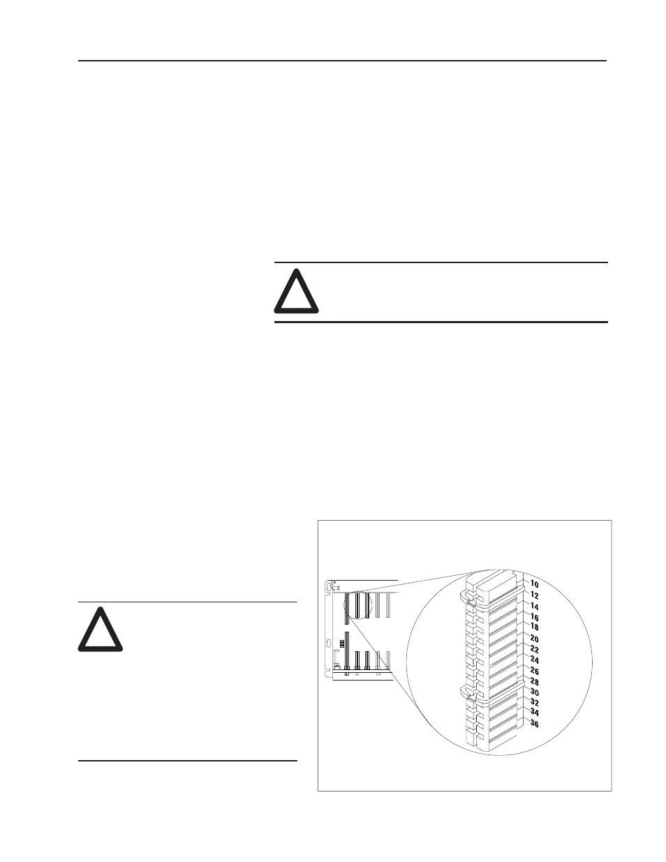
Key the Backplane Connector
Place your module in any slot in the chassis
except the leftmost slot which is reserved for
processors or adapters.
ATTENTION: Observe the
following precautions when
inserting or removing keys:
•
insert or remove keys with
your fingers
•
make sure that key placement
is correct
Incorrect keying or the use of a tool
can result in damage to the
backplane connector and possible
system faults.
!
Position the keying bands in the backplane connectors to correspond to
the key slots on the module.
Place the keying bands:
between 10 and 12
between 28 and 30
You can change the position of these bands if subsequent system design
and rewiring makes insertion of a different type of module necessary
.
Upper
Connector
11022ĆI
I/O chassis
Calculate Power
Requirements
Determine Module
Placement in the I/O
Chassis