Monitoring channel status bits example -9, Monitoring channel status bits example – Rockwell Automation 1746-NT8 SLC 500 Thermocouple/mV Analog Input Module User Manual User Manual
Page 65
Publication 1746-UM022B-EN-P - January 2005
Programming Examples 5-9
Monitoring Channel Status Bits Example
S:1
15
COP
Copy File
Source
#N10:0
Dest
#O:1.0
Length
8
COP
#NT8_CH_CNF
FLL
Fill File
Source
0
Dest
#N10:20
Length
8
FLL
#NT8_CH0_STS_FLAGS
CLR
Clear
Dest
B3:7
0000000000000001<
CLR
B3:6
4
NT8_CHECKING_STS
COP
Copy File
Source
#I:1.0
Dest
#N10:30
Length
8
COP
#NT8_LAST_TEMP_READ
T11:0
DN
NT8_STS_CHECK_TMR/DN
EN
DN
TON
Timer On Delay
Timer
T11:0
Time Base
1.0
Preset
60<
Accum
10<
TON
NT8_STS_CHECK_TMR
T11:0
DN
NT8_STS_CHECK_TMR/DN
L
B3:6
4
NT8_CHECKING_STS
COP
Copy File
Source
#N10:10
Dest
#O:1.0
Length
8
COP
#NT8_CH_CNF
B3:6
4
NT8_CHECKING_STS
EN
DN
TON
Timer On Delay
Timer
T11:1
Time Base
1.0
Preset
7<
Accum
0<
TON
NT8_STS_CNF_TMR
0004
0000
0001
0002
0003
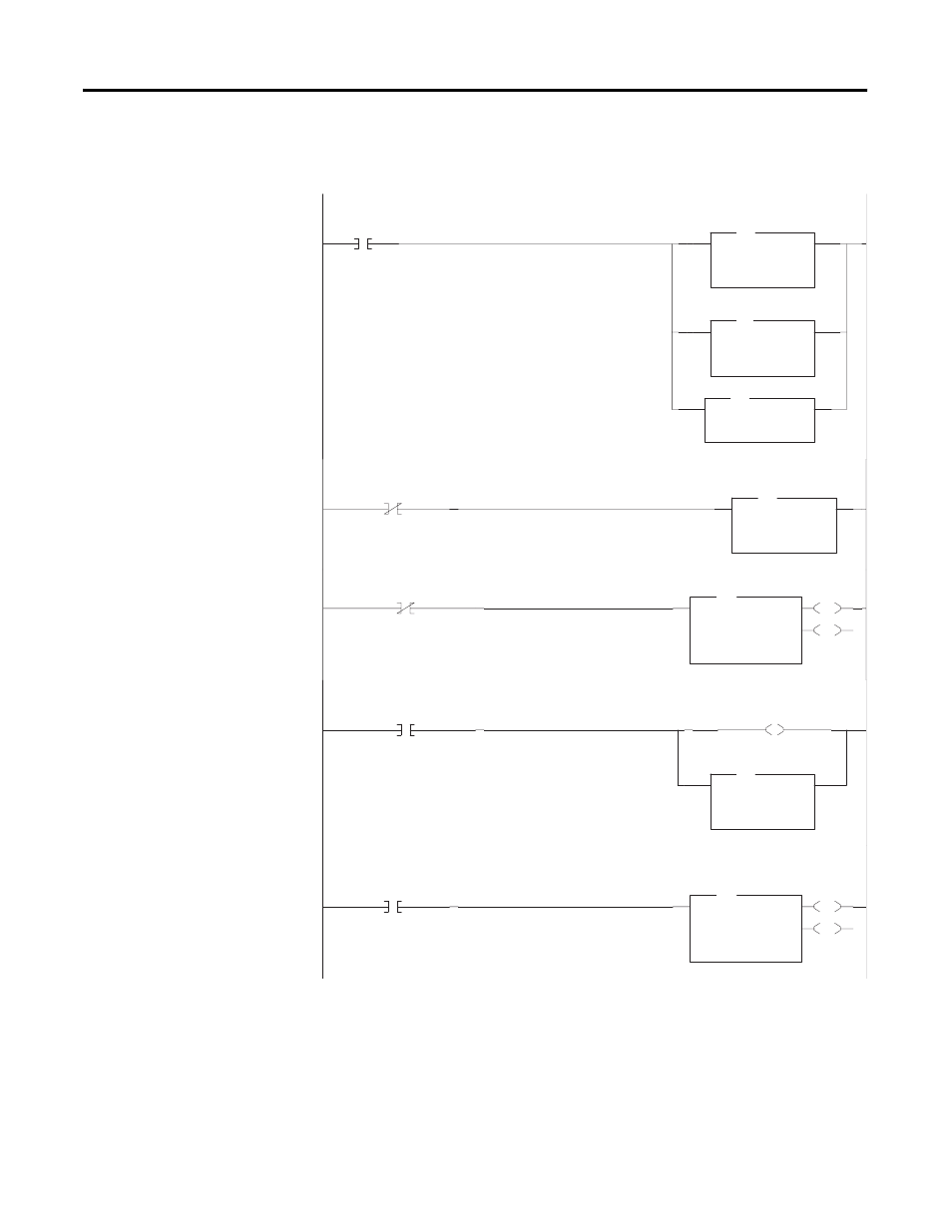
During 1st program scan, copy thermocouple channel configuration words (N10:0 - N10:7) to NT8. In addition, initialize
channel error registers (N10:20 - N10:27) and Error Flags (B3/119).
If the NT8 is not checking channel status, store the thermocouple readings in the NT8 last channel reading registers
(N10:37). These registers should be used in the remainder of the program (e.g. for temperature control) instead of the
NT8 I/O image location.
T11:0 is a repeating 60-second timer which initiates the NT8 channel status check.
Every 60 seconds, initiate a NT8 channel status check by latching the NTB channel status checking bit and copying
the “Status check” configuration words (N10:10 -N10:7) to the NT8 configuration words.
After copying the “Status Check configuration words” start a 7-second timer (T11:1) to allow the NT8 to update its I/O
image to the channel status words. The time required for the NT8 to update its I/O image is dependent on the NT8
configuration. Note, the time required to be greater than the channel update time including the auto calibration time.