Module addressing, Channel configuration – Rockwell Automation 1746-NT4 SLC 500 Thermocouple/mV Input Module Installation Instructions User Manual
Page 17
SLC™ 500 4-Channel Thermocouple/mV Input Module 17
Publication 1746-IN010D-EN-P - June 2004
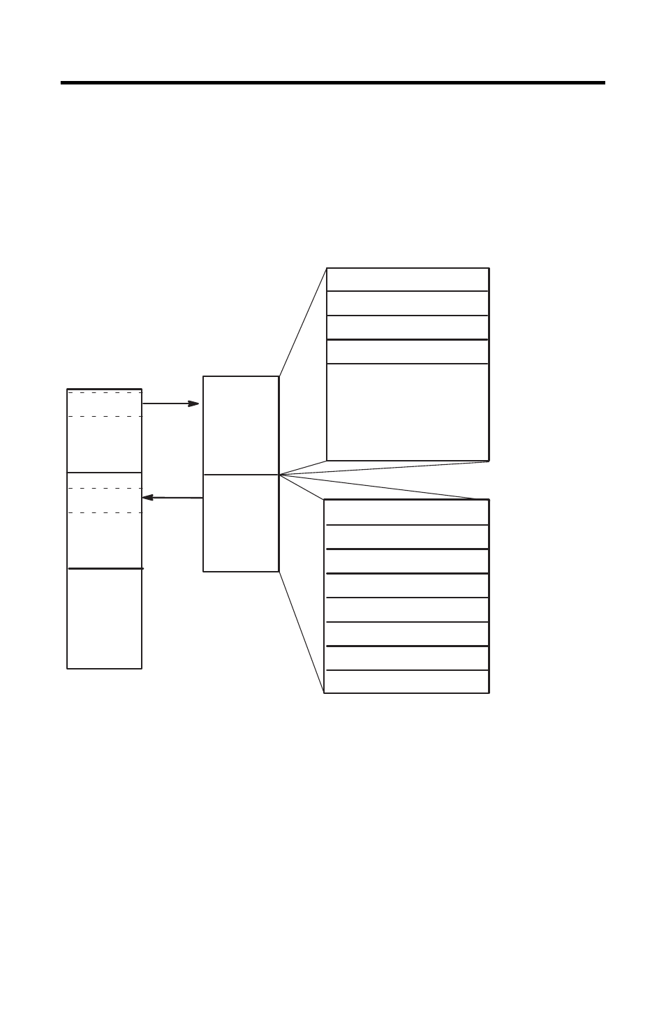
Module Addressing
The following memory map shows you how the output and input image tables are
defined for the thermocouple module.
Channel Configuration
Once the module is installed, each channel on the module can be configured to
establish the way the channel will operate. You configure the channel by entering
bit values into the configuration word using your programming software. Channels
0 through 3 on the NT4 are configured by entering bit values into output words 0
through 3 respectively. Output words 4 through 7 are not used. See the table on
page 18 for bit settings.
SLC 5/0X
Data Files
Slot e
Output Image
Slot e
Input Image
Output
Scan
Input
Scan
Thermocouple
Module Image
Output Image
8 Words
Input Image
8 Words
Output
Image
Input
Image
(Class 1)
Channel 0 Configuration Word
Channel 1 Configuration Word
Channel 2 Configuration Word
Channel 3 Configuration Word
Words 4-7
(not defined)
Channel 0 Data Word
Channel 1 Data Word
Channel 2 Data Word
Channel 3 Data Word
Channel 0 Status Word
Channel 1 Status Word
Channel 2 Status Word
Channel 3 status Word
Address
Bit 15
Bit 0
Address
Bit 15
Bit 0
Word 0
Word 1
Word 2
Word 3
O:e.0
O:e.1
O:e.2
O:e.3
Word 0
Word 1
Word 2
Word 3
Word 4
Word 5
Word 6
Word 7
I:e.0
I:e.1
I:e.2
I:e.3
I:e.4
I:e.5
I:e.6
I:e.7