Cold-junction compensation (cjc) – Rockwell Automation 1746-NT4 SLC 500 Thermocouple/mV Input Module Installation Instructions User Manual
Page 16
16 SLC™ 500 4-Channel Thermocouple/mV Input Module
Publication 1746-IN010D-EN-P - June 2004
4. At the other end of the cable, cut the drain wire and foil shield back to the
cable and apply shrink wrap.
5. Connect the signal wires to the NT4 terminal block and the input.
6. Repeat steps 1 through 5 for each channel on the NT4 module.
Cold-Junction Compensation (CJC)
To obtain accurate readings from each of the channels, the cold-junction
temperature (temperature at the module’s terminal junction between the
thermocouple wire and the input channel) must be compensated for. Two cold-
junction compensating thermistors have been integrated in the removable terminal
block; they must remain installed to retain accuracy.
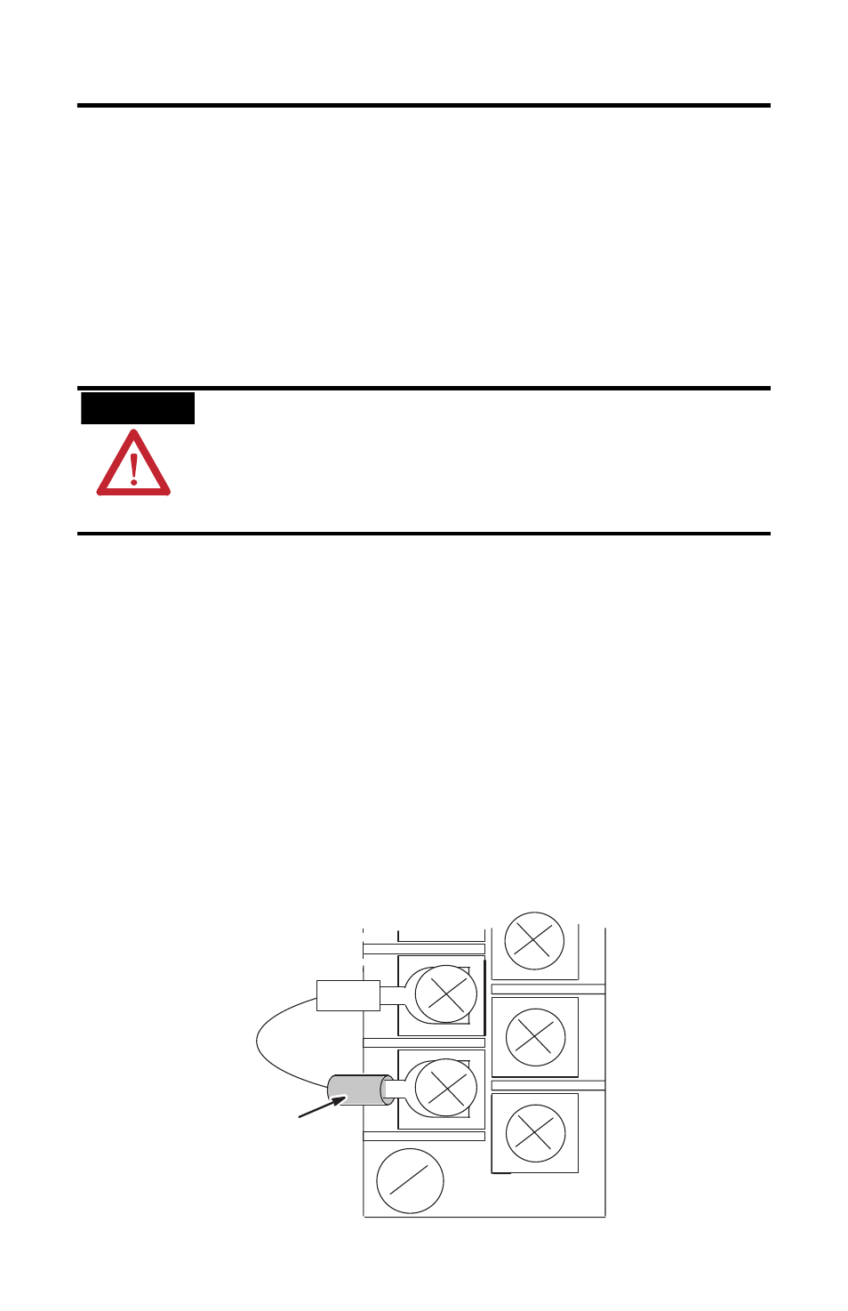
In case of accidental removal of either or both of the thermistor assemblies, make
sure to replace them by connecting each one across the CJC terminals located at the
top and bottom left side of the terminal block. When connecting the thermistor
assembly at the top of the terminal block (between terminals CJC A+ and CJC A-),
the lug containing the thermistor (marked with red epoxy) should attach to the
uppermost screw terminal (CJC A+). When connecting the thermistor assembly at
the bottom of the terminal block (between terminals CJC B+ and CJC B-), the lug
containing the thermistor should attach to the lowermost screw terminal (CJC B+).
ATTENTION
Do not remove or loosen the cold junction compensating
thermistor assemblies located between the two upper and
lower CJC terminals on the terminal block. Both thermistor
assemblies are critical to ensure accurate thermocouple input
readings at each channel. The module will not operate in the
thermocouple mode if either assembly is removed.
CJC
Assembly
Thermistor
(Always attach red lug to
the CJC+ terminal.)
Bottom of Terminal Block