Figure 3 -- example of controlnet network topology – Rockwell Automation 1788-CNFR ControlNet Daughtercard Installation Instructions User Manual
Page 10
10 ControlNet Daughtercard
Publication 1788-IN005A-EN-P - March 2001
To wire the module:
•
Hold down the latch and insert the Channel A zipcord connector into the
duplex socket until the pins and latch lock into place (see the illustration
below).
Make sure you insert the blue pin (receive) of the zipcord connector into the
left Rx and the black pin (transmit) into the right Tx socket.
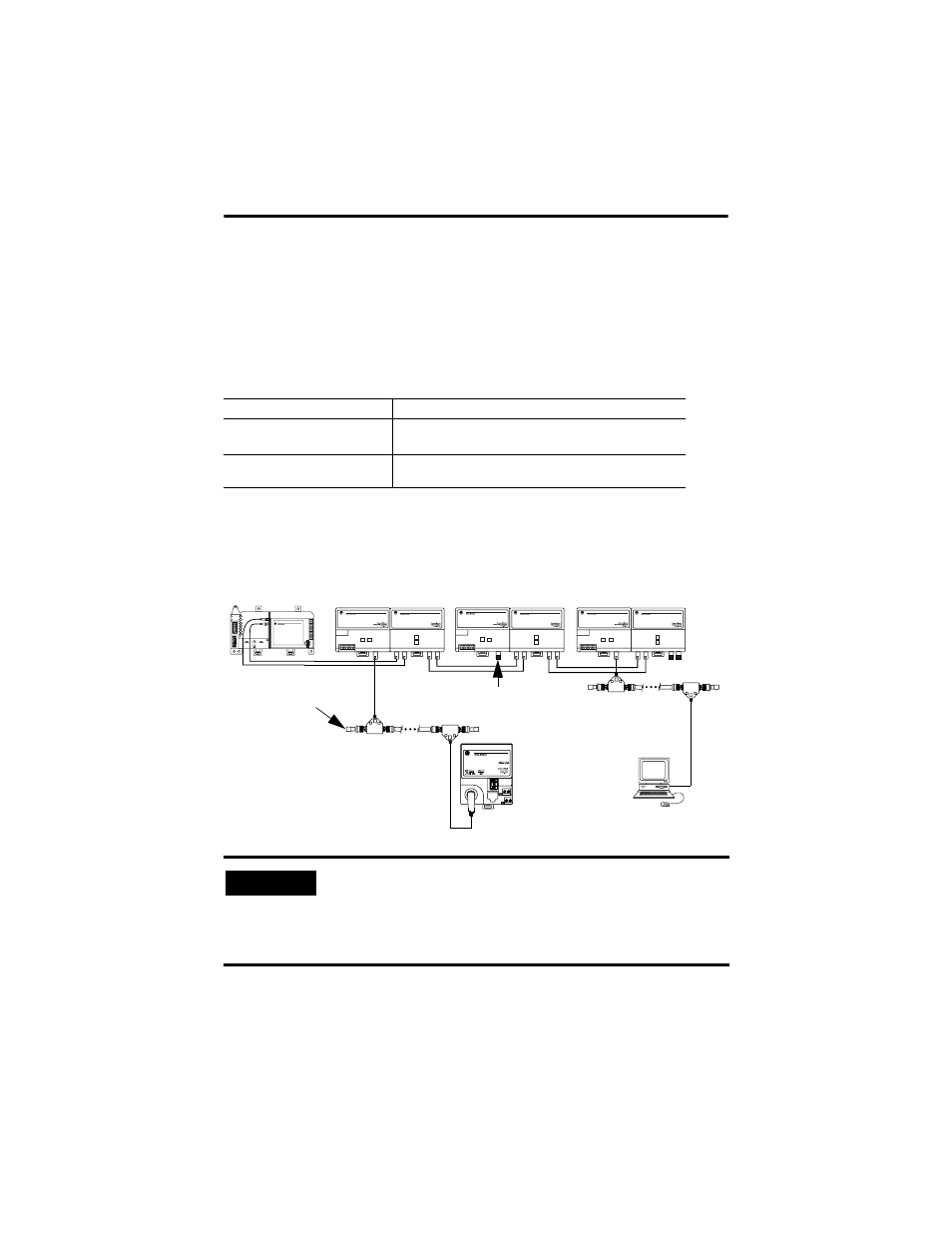
Figure 3 -- Example of ControlNet Network Topology
If your network supports
Connect the fiber cable
nonredundant media
(1788-CNF or -CNFR)
to the channel A connector on the module
(channel B on the 1788-CNFR is not used.)
1
redundant media
(1788-CNFR)
from trunk-cable A to channel A on the 1788-CNFR and from
trunk-cable B to channel B on the 1788-CNFR.
1.
Rockwell Automation recommends using channel A for non-redundant media.
IMPORTANT
It is not necessary to install nodes on coax segments. If you are
only using the repeaters to extend, then install a 75-
Ω
terminator
(1786-XT) on the BNC coax connector on the fiber repeater
adapter (1786-RPA). This should be done to all repeaters that are
not connected to coax segments.
ACN
A
Fiber segment 1
example ControlNet Node
1786-RPFS
XT terminator
42834
1786-RPA
1786-RPFS
1786-RPA
1786-RPFS
1786-RPA
Tx
Rx
Tx
Tx
Tx
Tx
Tx
Rx
Rx
Rx
Rx
Rx
Rx
Tx
CH1
CH1
CH1
CH2
CH2
CH2
XT terminator
Fiber segment 2
Fiber segment 3
Coax segment 2
Coax segment 1
example ControlNet Node