Plc-5 family processors, Programming examples appendix b – Rockwell Automation 1771-IXHR , D17716.5.80 HIGH RESOL.THERMOCOUPLE User Manual
Page 52
Programming Examples
Appendix B
BĆ2
4. When you have entered your data, press [ENTER]. If you make a mistake,
make sure the cursor is over the word you desire to change. Enter the
correct data and press [ENTER].
Figure B.2
Write Block Transfer for a PLC-3 Processor
00000000 00000000
00000000 00000000
00000000 00000000
00000000 00000000
00000000 00000000
00000000 00000000
00000000 00000000
00000000 00000000
00000000 00000000
00000000 00000000
00000000 00000000
00000000 00000000
00000000 00000000
00000000 00000000
00000000 00000000
00000000 00000000
00000000 00000000
00000000 00000000 00000000 00000000
00000000 00000000
00000
00004
00010
00014
00020
WORD #
0
1
2
3
START - W0003 : 0000
DATA MONITOR
PROG : I/O OFF NO FORCES : NO EDITS : RUNG # [RM000000] : MEM PROT OFF
$ W03:0 - [ ]
5. Press [CANCEL COMMAND]. This returns you to the ladder diagram.
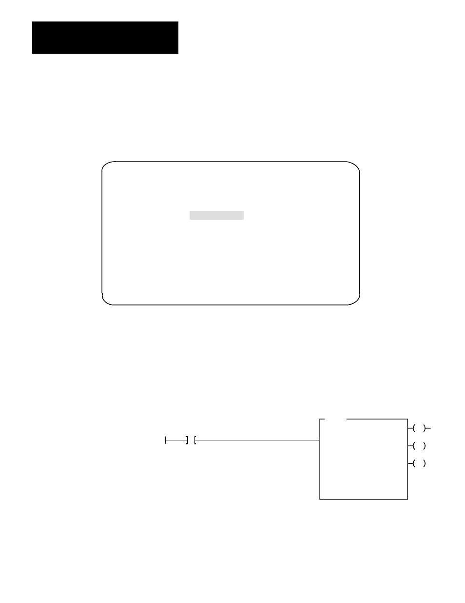
The following is a sample procedure for entering data in the configuration
words of the block transfer write instruction when using a PLC–5 processor. For
a complete sample program, refer to figure 4.3.
1. Enter the following rung:
EN
BTW
BLOCK XFER WRITE
RACK:
GROUP:
MODULE:
CONTROL:
0
0
0
N7:0
DN
DATA FILE:
LENGTH:
CONTINUOUS:
N7:60
27
N
ER
Power Up Bit
N7:60 is the address of the BTW transfer file.
2. Press [F8],[F5] and enter N7:60 to display the configuration block.
The industrial terminal screen should like Figure B.3.
PLC-5 Family Processors