Module data, status, and channel configuration, Module memory map, Accessing input image file data – Rockwell Automation 1762-IT4 Thermocouple/mV Input Module User Manual
Page 31: Chapter 3, Module, Accessing input image file data -1, Chapter
1
Publication 1762-UM002A-EN-P - July 2002
Chapter
3
Module Data, Status, and Channel
Configuration
After installing the 1762-IT4 thermocouple/mV input module, you
must configure it for operation using the programming software
compatible with the controller (for example, RSLogix 500). Once
configuration is complete and reflected in the ladder logic, you need
to operate the module and verify its configuration.
This chapter contains information on the following:
•
module memory map
•
accessing input image file data
•
configuring channels
•
determining effective resolution and range
•
determining module update time
Module Memory Map
The module uses six input words for data and status bits (input
image), and five configuration words.
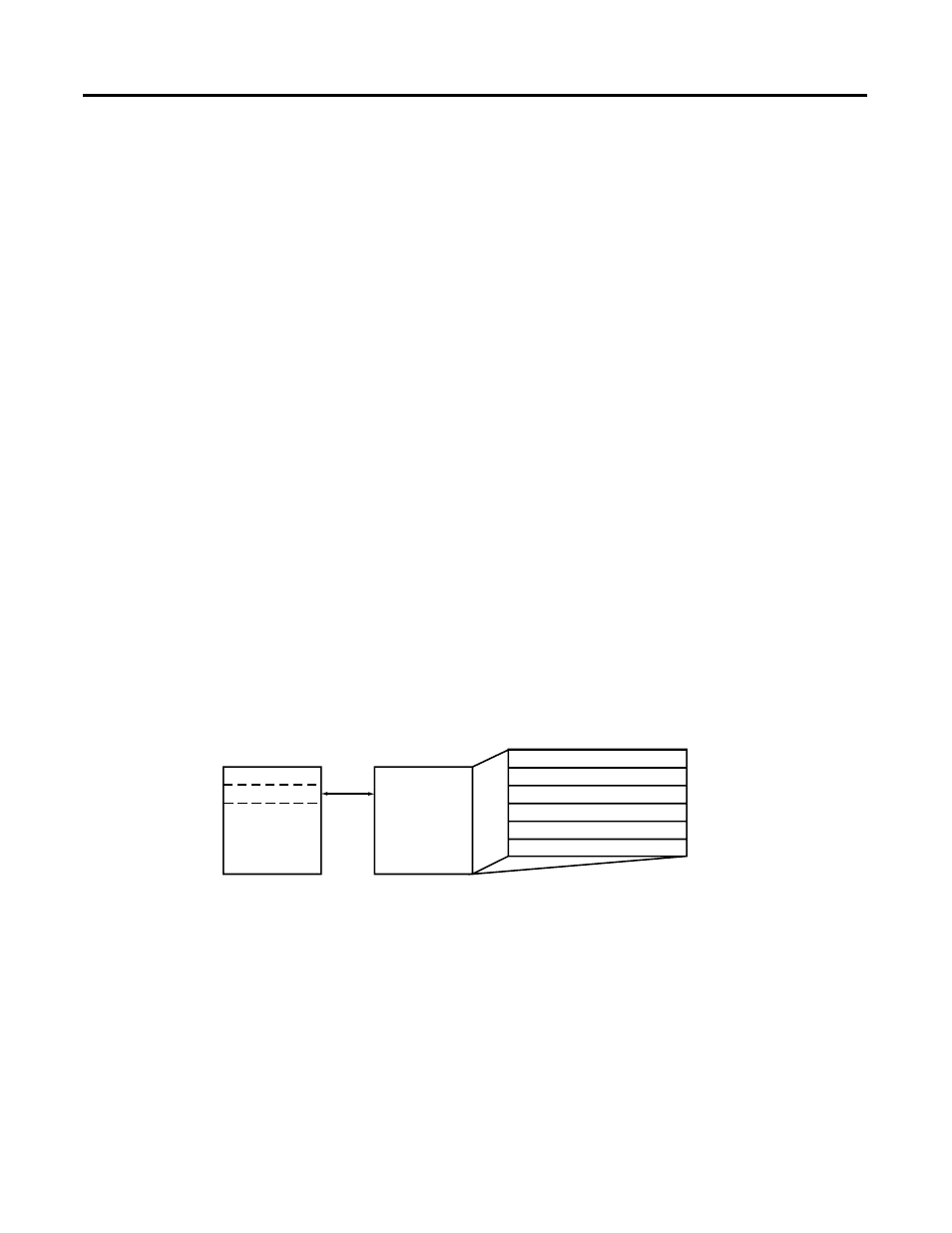
Accessing Input Image File
Data
The input image file represents data words and status words. Input
words 0 through 3 hold the input data that represents the value of the
analog inputs for channels 0 through 3. These data words are valid
only when the channel is enabled and there are no errors. Input
words 4 and 5 hold the status bits. To receive valid status information,
the channel must be enabled.
You can access the information in the input image file using the
programming software data files input screen.
Channel 0 Data Word
Word 0
Word 1
Word 2
Word 3
Word 4, bits 0 to 4 and 8 to 12
Word 5, bits 6 to 15
Channel 1 Data Word
Channel 2 Data Word
Channel 3 Data Word
General/Open-Circuit Status Bits
Over-/Under-range Bits
Input Image
6 words
slot e
Input Image
File
Memory Map
Bit 15
Bit 0