Preparing low voltage door for 825 plus – Rockwell Automation 1500 Modular Protection System Conversion Kit (Bulletin 1406 to Bulletin 825 Plus) User Manual
Page 17
1500-IN058D-EN-E – June 2013
Installation
4-5
Preparing Low Voltage Door
for 825 Plus
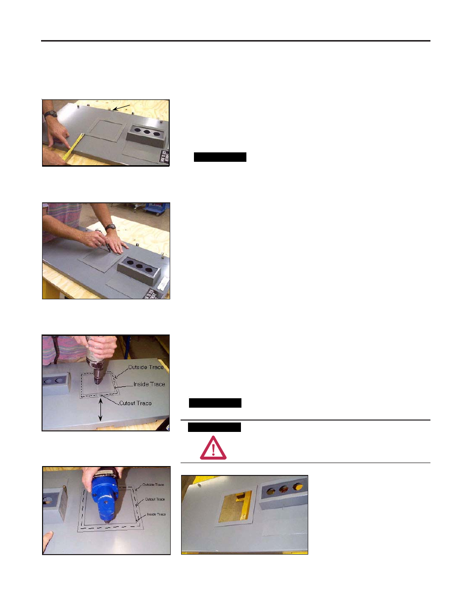
1. Once the door has been removed, place the door on a level work
surface.
2. Position an 825 Plus Mounting Collar squarely on the low
voltage door to locate the required cutout. (Figure 4.10)
Position the 825 Plus cutout on the door properly to
ensure that the low voltage door and low voltage
panel can swing open without difficulty. It is
recommended that the edge of the cutout be
positioned at least 5 inches (127 mm) from the
unhinged side of the low voltage door, to allow for
proper clearance to open the low voltage door with
the 825 Plus installed.
3. Using the collar as a template, lightly trace the cutout area on the
inside and outside of the collar. This outline represents the
minimum and maximum size required by the 825 Plus relay.
(Figure 4.11)
4. Drill a pilot hole in the center of the traced cutout area.
(Figure 4.12)
5. Double-check the measurements before cutting. With a cutting
tool, cut on the outside edge of the inside cutout trace.
(Figure 4.13)
6. To ensure the hole is of the correct size, place a mounting collar
over the hole. There should be no metal showing on the inside of
the collar, and the collar should not pass through the cutout.
(Figure 4.14)
Remove all metal chips before mounting the 825 Plus.
Failure to remove all metal chips can result in
equipment damage or hazardous operation.
Figure 4.10
Hinge Side
Figure 4.11
Figure 4.12
Min. 5"
Figure 4.13
Figure 4.14
A T T E N T I O N
A T T E N T I O N
I M P O R T A N T
I M P O R T A N T
I M P O R T A N T
I M P O R T A N T