825 plus interface panel – Rockwell Automation 1500 Modular Protection System Conversion Kit (Bulletin 1406 to Bulletin 825 Plus) User Manual
Page 14
1500-IN058D-EN-E – June 2013
4-2
Installation
825 Plus Interface Panel
Disconnect and lockout all sources of power entering the
low voltage compartment where the 1406-P16 is located.
This may include opening the main disconnect isolation
switch. Failure to disconnect and lock out power can
result in personal injury and/or damage to the equipment.
1. Disconnect the control wires connected to the 1406-P16. Using the
wire number table in Appendix A, mark each wire with the
corresponding 1406 terminal block number for reference later in the
procedure.
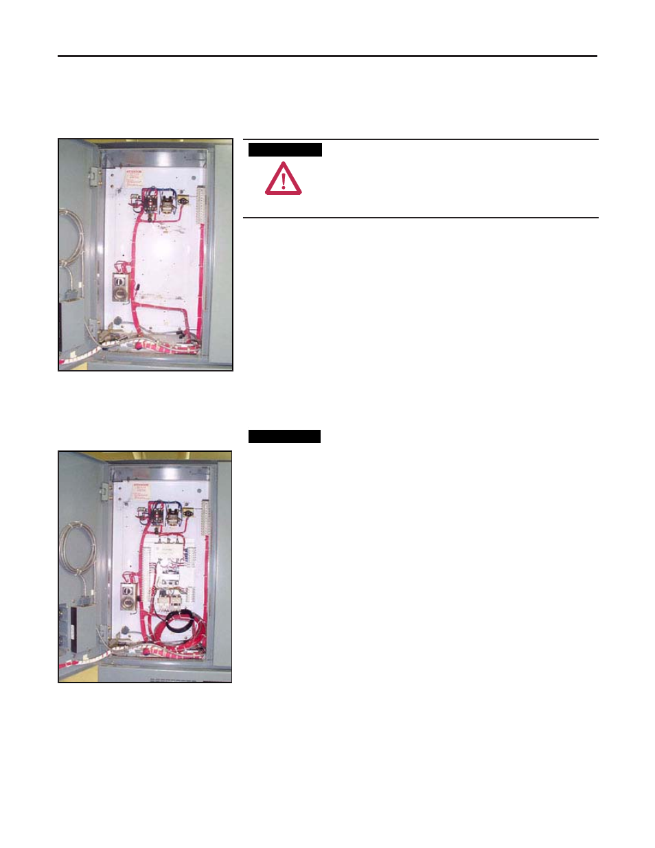
2. Remove the 1406-P16 module from the low voltage panel. Save all
the mounting hardware. (Figure 4.1)
3. Use the saved mounting hardware from the previous step to mount
the 825 Plus Interface Panel in the same location the 1406 occupied.
(Figure 4.2)
If a 1406-R16 RTD module was used with the 1406-P16,
the RTD module must also be removed. The RTD
wiring to the old 1406 RTD module must be rewired to
the 825 Plus RTD Panel. Refer to the 825 Plus RTD
Panel Installation Guide (Appendix C). Handle existing
wiring with care. Replace any damaged or worn wiring.
Figure 4.1
Figure 4.2
A T T E N T I O N
A T T E N T I O N
I M P O R T A N T
I M P O R T A N T