Rockwell Automation 1395 Node Adapter Board User Manual
Page 15
Chapter 3
Functional Description
3-3
Data required by the drive on a continuously updated basis is sent (to the
drive) using the method of data transfer described above. The rate of data
transfer is determined by the standard conventions for determining the I/O
update interval of the I/O scanner for the particular PLC Controller used.
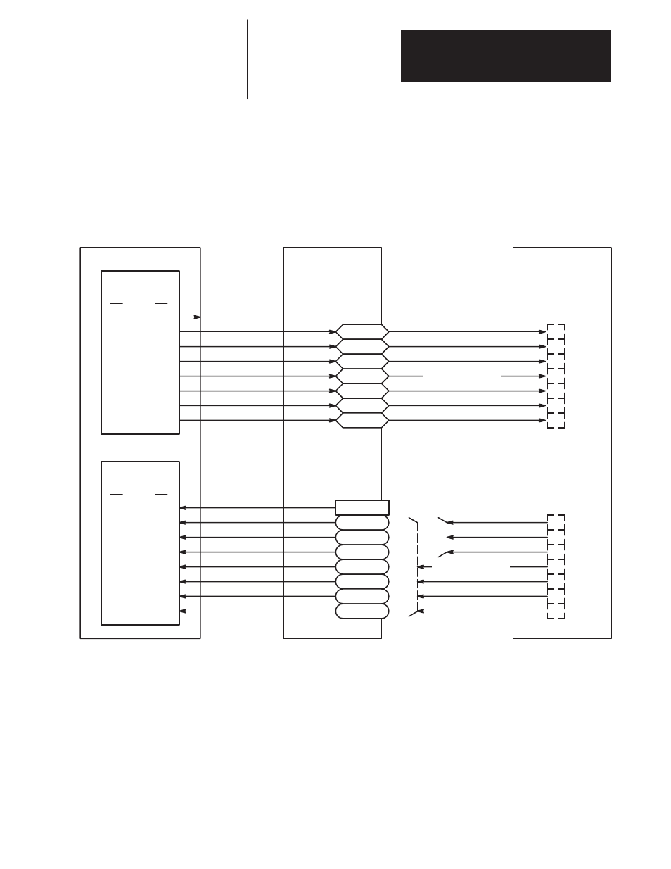
Figure 3.1
Node Adapter Configuration Variables
Node Adapter Board
300/400
301/401
302/402
303/403
304/404
305/405
306/406
Reserved for
Block Transfer
PLC Controller
Output Image Table
Group Number
Full
Half
0
1
2
3
4
5
6
7
0/4
1/5
2/6
3/7
Input Image Table
Group Number
Full
Half
0
1
2
3
4
5
6
7
0/4
1/5
2/6
3/7
NA Status
350/450
351/451
352/452
353/453
354/454
355/455
356/456
Block Transfer
Port B/A
Port B/A
1
2
3
4
5
6
7
1
2
3
4
5
6
7
User Configurable
Soft Links
Half
Rack
Full
Rack
Sinks
Output
Variables
Input
Variables
Bulletin 1395 Drive
Sources
User Configurable
Soft Links
Discrete PLC Controller I/O Example
Figure 3.2 illustrates an application where the Node Adapter Board has
been setup for a full rack (numbered rack 2) and the 16 bit words for group
1 and 2 are being used by the PLC Controller program for data transfer
with the drive. In this example, the drive has been configured so that the
data coming into source parameter 300 is sent to Logic Cmd 1 (Parameter
150). Information sent to the drive using the 16 bit output word for group 1
of rack 2 must therefore be a 16 bit logic word where the bits are defined
by the description of Parameter 150.