E - doc cleaning and maintenance, Contact resistance, Vacuum interrupter integrity test – Rockwell Automation 1102C-BOx93 Vacuum Contactor (200A) User Manual
Page 6: Wiring, G. ushakow
42052-087
G. Ushakow
N/A
N/A
N/A
42052
1006490
1
INSTRUCTION SHEET
BULLETIN 1102C VACUUM CONTACTOR
CURRENT RATINGS 200A
200V-1500V
2-20-04
Mark Jutz
2-20-04
D. Josef
2-20-04
6
9
REVISION
AUTHORIZATION
DIMENSIONS APPLY BEFORE
SURFACE TREATMENT
H
A
B
C
D
E
F
G
(DIMENSIONS IN INCHES)
TOLERANCES UNLESS
OTHERWISE SPECIFIED
REFERENCE
SHEET
OF
DWG.
B
DR.
CHKD.
APPD.
DATE
DATE
DATE
±
±
±
ANGLES:
.XXX:
.XX:
THIS DRAWING IS THE PROPERTY OF
THE ALLEN-BRADLEY CO. INC.
AND MAY NOT BE COPIED, USED OR
DISCLOSED FOR ANY PURPOSE EXCEPT
AS AUTHORIZED IN WRITING BY
THE ALLEN-BRADLEY CO. INC.
LOCATION : MILWAUKEE,
WISCONSIN
U.S.A.
SIZE
1
2
3
4
5
6
7
8
E - DOC
Cleaning and Maintenance
1. The vacuum contactor requires no adjustment. Preventative maintenance is recommended on a routine basis, once every twelve
months, dependent upon the environment that the contactor is exposed to. In general, maintenance consists of keeping the device free of
dirt and dust and ensuring the power and control terminals are tight.
2. Maintenance should verify the mechanical operation of the device for freedom of movement. Clean dirt from the surfaces. Pay
particular attention to molded parts and tracking surfaces. Foreign materials on these surfaces should be removed by vacuum or wiping.
Do not use compressed air to remove foreign materials.
ATTENTION:
The following test should be performed using a 50/60 Hz test set. Where the voltage is continuously variable up to at least
20 kV. X-radiation at this level is negligible. However, personnel should not be closer than ten feet to the interrupter and the test cables to
avoid high voltage shock hazards. The contactor should be free of dust and other contaminants before conducting this test.
Contact Resistance
A contact resistance test can be performed using a micro-ohmeter. This test determines the condition of contact surfaces. With the
contactor closed, the resistance across the terminals should be less than 400 micro-ohms. If higher contact resistance values are
measured then a high potential test should be performed, as follows:
1. Disconnect the line and load conductors from the contactor.
2. Connect the leads of the test set across the interrupter terminals with the contactor in the open position.
3. Slowly raise the voltage to 10 KV and hold for 15 seconds.
4. The leakage current should not exceed 5 MA during the test and any tripping of the test set circuit protector during the test should be
repeated two to three times. If it becomes impossible to reach the 10 KV level, then the interrupter needs to be replaced, and should be
replaced by utilizing an Allen-Bradley replacement phase assembly kit.
ATTENTION: Excercise caution while performing high voltage potential tests.
Vacuum Interrupter Integrity Test
1. A high potential test will determine the di-electric strength and condition of the vacuum interrupter. A high potential test should be
performed on each vacuum interrupter phase in sequence and should be performed approximately once every twelve months.
2. The vacuum interrupter integrity test should be performed if the contactor has been known to be exposed to fault conditions - either
phase to phase or phase to ground.
3. When doing this check, make visual inspection for physical evidence of stress, distorted, discolored or cracked interrupters.
4. A contact resistance test can be done as defined below or if preferred a high potential test; di-electric test should be performed as
follows.
(6)
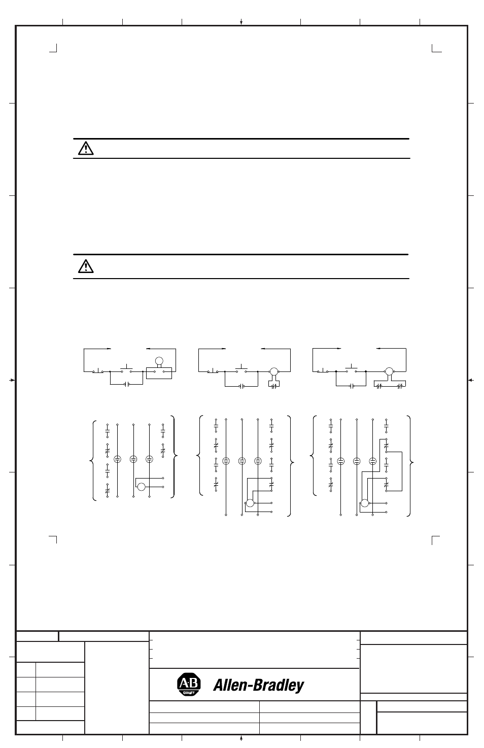
Wiring
T1
T2
T3
(A1)
(A2)
(82)
(81)
O
P
T
IO
N
A
L
(
11
95
C
-N
3
O
R
1
19
5C
-N
4)
M
(74)
(73)
(62)
(22)
(61)
(54)
(21)
(14)
WIRING DIAGRAM
WIRING DIAGRAM
WIRING DIAGRAM
(53)
(13)
L3
L2
L1
(A2)
(A1)
(14)
(13)
M
START
STOP
M
SCHEMATIC
SEPARATE
AC SOURCE
(34)
(33)
M
START
STOP
SCHEMATIC
SCHEMATIC
SEPARATE
125V DC SOURCE
LATE
BREAK
(B2)
(B1)
(46)
(45)
M
(B1)
M
T3
T2
T1
(B2)
(82)
(81)
LATE
BREAK
(74)
(73)
(34)
(33)
(46)
(45)
O
P
T
IO
N
A
L
(
11
95
C
-N
3
O
R
1
19
5C
-N
4)
(62)
(61)
(54)
(22)
(21)
(14)
(53)
(13)
L1
L2
L3
(B1)
T3
T2
T1
(B2)
(82)
LATE
BREAK
M
(81)
(74)
(73)
(34)
(33)
LATE
BREAK
(62)
(61)
(54)
(26)
(53)
(25)
(46)
(45)
(14)
(13)
L1
L2
L3
O
P
T
IO
N
A
L
(
11
95
C
-N
3
O
R
1
19
5C
-N
4)
11
95
C
-N
6
C
O
N
T
R
O
L
P
A
K
11
95
C
-N
5
LATE
BREAK
(B2)
(B1)
M
(34)
(33)
(26)
(25)
(45)
(46)
M
START
STOP
SEPARATE
250V DC SOURCE