Rockwell Automation 1102C-BOx93 Vacuum Contactor (200A) User Manual
Page 5
42052-087
G. Ushakow
N/A
N/A
N/A
42052
1006490
1
INSTRUCTION SHEET
BULLETIN 1102C VACUUM CONTACTOR
CURRENT RATINGS 200A
200V-1500V
2-20-04
Mark Jutz
2-20-04
D. Josef
2-20-04
5
9
REVISION
AUTHORIZATION
DIMENSIONS APPLY BEFORE
SURFACE TREATMENT
H
A
B
C
D
E
F
G
(DIMENSIONS IN INCHES)
TOLERANCES UNLESS
OTHERWISE SPECIFIED
REFERENCE
SHEET
OF
DWG.
B
DR.
CHKD.
APPD.
DATE
DATE
DATE
±
±
±
ANGLES:
.XXX:
.XX:
THIS DRAWING IS THE PROPERTY OF
THE ALLEN-BRADLEY CO. INC.
AND MAY NOT BE COPIED, USED OR
DISCLOSED FOR ANY PURPOSE EXCEPT
AS AUTHORIZED IN WRITING BY
THE ALLEN-BRADLEY CO. INC.
LOCATION : MILWAUKEE,
WISCONSIN
U.S.A.
SIZE
1
2
4
5
6
7
8
E - DOC
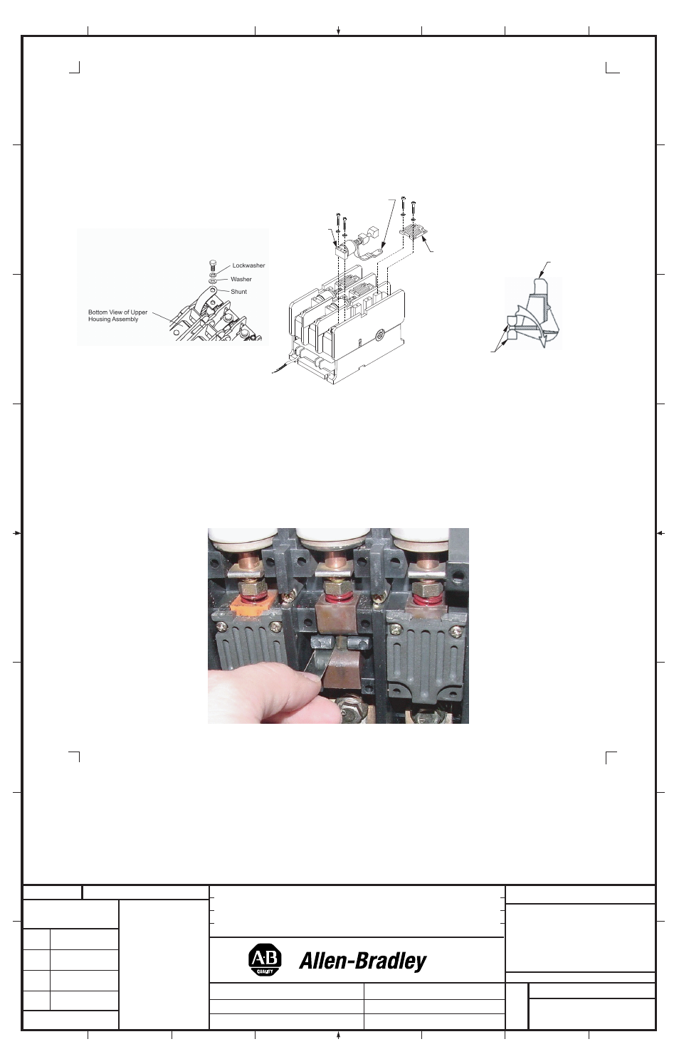
Figure 7A
Contact Life Over Travel Measurement
The purpose of this measurement is to determine how much vacuum interrupter electrical life remains on the contact and is performed using a
standard wire gauge in a "go, no go" check.
1. De-energize the contactor and isolate from all power sources. The control source can be maintained if coming from a separate supply or if
taken from a line to line connection by application then an additional control source needs to be connected to terminals A1 and A2. Re-
energize the contactor insuring that the main power circuits are open and isolated.
2. Remove Phase Cover as described (Figure 3A) page 2, earlier to access inspection area (Figure 8).
Figure 8
(5)
Vacuum Interrupter Phase Assembly Replacement Instructions (Cont'd)
8. Place the new Interrupter Phase Assembly into the upper housing. Be sure that the Cams are properly seated around the Contact Operator.
Thread the Shunt through the housing and Contact Operator, following the Shunt path
(Figure 7C). Replace the hardware securing the
Interrupter Phase Assembly
(Figure 7B). Tighten screws to 60 - 80 lb-inches. The replacement interrupter is factory set for contact gap and
does not require adjustment in the field. Attach the Shunt to the load terminal by placing the Shunt against the terminal with the flat washer
and lock washer between the Shunt and the head of the bolt
(Figure 7A) and tighten until the lock washer is fully compressed (or up to 60 lb-
inches). Replace the Cam Cover and hardware (tighten to 60 - 80 lb-inches). Reinstall the Cover and secure it with the original mounting
hardware. Tighten the four screws in a diagonal pattern to 5 lb- inches
(Figure 3A). Reattach the coil wire leads to the Control-Pak (tighten to
7 - 9 lb-inches). Reinstall the device and reconnect any auxiliary control wires. Reconnect the line and load conductors and tighten the main
terminal hardware and bolts to 132 lb-inches.
3. When the contactor is closed, a gap occurs, and this gap should accept a standard wire (.010") gauge. If the gauge can be inserted in the
space then sufficient life remains for an additional 100,000 operations. Check all phases.
4. If the .010" wire gauge cannot be inserted into this gap with the contactor energized, then over travel has been exhausted and thus contact
life used up. The contactor should be replaced.
Figure 7B
Figure 7C
Cam
Cover
Interrupter
Phase Assembly
Shunt
Shunt Path
Cam
Orientation
Contact
Operator