Installation instructions, E - doc, Coil replacement instructions – Rockwell Automation 1102C-BOx93 Vacuum Contactor (200A) User Manual
Page 2
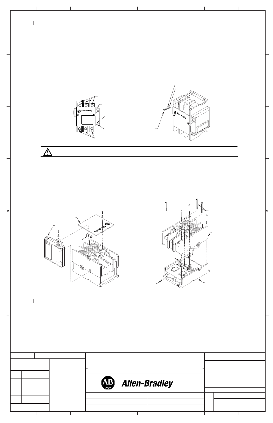
Line Terminals
Control Pak
1/4 Flat
Washer
1/4 Lock Washer
1/4" or 7mm Bolt
Coil
Terminals
Load Terminals
A1
A2
Installation Instructions
The vacuum contactor may be used in any mounting plane. In any non-horizontal mounting plane, the top of the contactor should point up
(so that the label appears right-side up). Care should be taken to insure that the mounting hardware does not warp the mechanism frame. If
the surface of the contactor to which the contactor is mounted is twisted, shims should be used to correct the condition. Any appreciable
degree of end to end twist will result in phase to phase discrepancies and timing of the main contact could cause increased pickup in control
voltage values.
1. Figure 1 illustrates the field terminals for line and load terminations. Mount the contactor with the hardware specified in Figure 2. Loosely
install the (4) mounting bolts into the intended mounting surface. Torque the mounting bolts to 50-75 lb-inches.
2. Connect control wires to the vacuum contactor control terminals A1 and A2 located on the Control-Pak using #18 to #12 gauge 75°C
stranded copper or tin stranded copper wire tightening screw terminals to 7 lb-inches torque.
3. Using 75°C wire copper cable, connect the line and load conductors to the main terminals (Figure 1) and proper phase rotation, tighten the
main terminal bolts to 132 lb-inches torque.
4. Check all connections for accuracy and mechanical connection before energizing.
42052-087
G. Ushakow
N/A
N/A
N/A
42052
1006490
1
INSTRUCTION SHEET
BULLETIN 1102C VACUUM CONTACTOR
CURRENT RATINGS 200A
200V-1500V
2-20-04
Mark Jutz
2-20-04
D. Josef
2-20-04
2
9
REVISION
AUTHORIZATION
DIMENSIONS APPLY BEFORE
SURFACE TREATMENT
H
A
B
C
D
E
F
G
(DIMENSIONS IN INCHES)
TOLERANCES UNLESS
OTHERWISE SPECIFIED
REFERENCE
SHEET
OF
DWG.
B
DR.
CHKD.
APPD.
DATE
DATE
DATE
±
±
±
ANGLES:
.XXX:
.XX:
THIS DRAWING IS THE PROPERTY OF
THE ALLEN-BRADLEY CO. INC.
AND MAY NOT BE COPIED, USED OR
DISCLOSED FOR ANY PURPOSE EXCEPT
AS AUTHORIZED IN WRITING BY
THE ALLEN-BRADLEY CO. INC.
LOCATION : MILWAUKEE,
WISCONSIN
U.S.A.
SIZE
1
2
3
4
5
6
7
8
E - DOC
ATTENTION: If coil failure is suspected, check that secondary damage has not occurred that will render the contactor non-repairable.
Figure 3A
Figure 3B
Figure 1
Figure 2
(2)
Control-Pak
Cover
Retainer
Contact
Operator
Center
Screws
Lower
Housing
Upper
Housing
Return
Springs
VAC
UUM
CO
NTA
CTO
R
VAC
UUM
CON
TAC
TOR
Coil Replacement Instructions
1. Disconnect all power cables (or bus work) and all control wiring to the contactor.
2. Remove the contactor from its mounted location. The contactor is best serviced in the benchtop position as shown.
3. Remove the cover attachment screws from the contactor and remove the Cover and Retainer (Figure 3A).
4. Disconnect the two wire leads from the Coil to the Control-Pak. Remove the Control-Pak from the contactor and set on benchtop (Figure 3B).
5. Remove the (6) screws that secure the Upper Housing to the Lower Housing by first removing the (4) outer screws and then (2) center
screws. NOTE- Removing the center screws will release the Return Springs. Carefully remove the Upper Housing leaving the Return Springs
in the Lower Housing
(Figure 3B)).
VACUUM CONTACTOR