Shroud – Rockwell Automation 1204-TFB2 Terminator User Manual
Page 8
8
1204 Terminator (Class 1, Division 2)
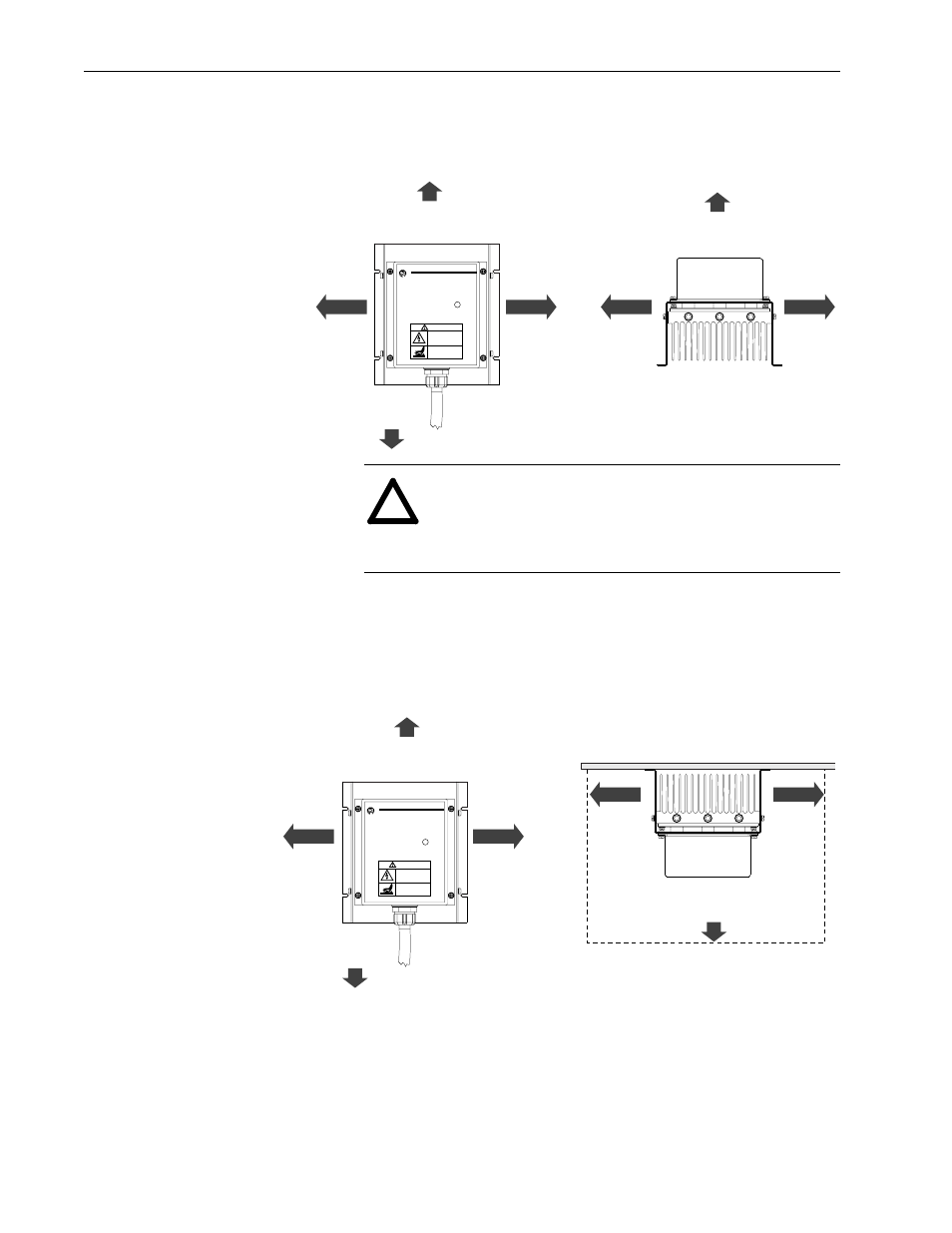
3. You must allow at least 152.4 mm (6 in.) on each side of the unit
and 304.8 mm (12 in.) on the top and bottom of the unit for
proper air circulation.
4. If your system consistently runs at line voltages above nominal
and you are mounting the terminator in a high-traffic area where
the potential for contact is high, you should place a shroud of
expanded metal or mesh screen around the terminator. The shroud
should not restrict air flow to the terminator, nor should it be
closer than 152.4 mm (6 in.) to the terminator at any point.
5. Connect the red, white and black cable conductors to the
corresponding three-phase motor leads/terminals.
6. Attach the green cable conductor to the motor ground that is
connected directly to the drive PE terminal.
Front View
Top View
Allen-Bradley
Motor Terminator
152.4 mm
(6.0 in.)
152.4 mm
(6.0 in.)
304.8 mm
(12.0 in.)
304.8 mm
(12.0 in.)
152.4 mm
(6.0 in.)
152.4 mm
(6.0 in.)
152.4 mm
(6.0 in.)
DANGER
CAN CAUSE SHOCK,
BURNS, OR DEATH
DISCONNECT AND LOCKOUT
ALL POWER SOURCES
BEFORE SERVICING
SURFACES
MAY BE HOT
ALLOW TO COOL
BEFORE SERVICING
Assembled in Mexico
See Instruction Manual For Mounting Instructions
Bulletin 1204–TFXX Series A
AC Drive HP ZZZZ
Voltage WWWW VAC
Max. Carrier Freq. Y KHz
Type 4X Enclosure
Hazardous Locations
Class I, Division 2
Groups A, B, C, D
Temperature Code T3 (200˚ c)
UL
®
C
US
LISTED
IND. CONT. EQ.
FOR USE IN HAZ. LOC.
8AA4
!
ATTENTION: The terminator surfaces may be hot enough
to cause serious burns. If your system consistently runs at
line voltages above nominal, you should place a shroud
around the terminator to prevent accidental exposure.
Front View
Top View
Allen-Bradley
Motor Terminator
Shroud
Shroud
152.4 mm
(6.0 in.)
152.4 mm
(6.0 in.)
152.4 mm
(6.0 in.)
152.4 mm
(6.0 in.)
152.4 mm
(6.0 in.)
152.4 mm
(6.0 in.)
152.4 mm
(6.0 in.)
DANGER
CAN CAUSE SHOCK,
BURNS, OR DEATH
DISCONNECT AND LOCKOUT
ALL POWER SOURCES
BEFORE SERVICING
SURFACES
MAY BE HOT
ALLOW TO COOL
BEFORE SERVICING
Assembled in Mexico
See Instruction Manual For Mounting Instructions
Bulletin 1204–TFXX Series A
AC Drive HP ZZZZ
Voltage WWWW VAC
Max. Carrier Freq. Y KHz
Type 4X Enclosure
Hazardous Locations
Class I, Division 2
Groups A, B, C, D
Temperature Code T3 (200˚ c)
UL
®
C
US
LISTED
IND. CONT. EQ.
FOR USE IN HAZ. LOC.
8AA4