Mounting orientations – Rockwell Automation 1606-XLDC92D Power Supply Reference Manual User Manual
Page 20
All parameters are specified at 24V, 3.8A, 24Vdc input voltage, 25°C ambient and after a 5 minutes run-in time, unless noted otherwise.
20
Rockwell Automation Publication 1606-RM023A-EN-P — January 2014
Bulletin 1606 Switched Mode Power Supplies
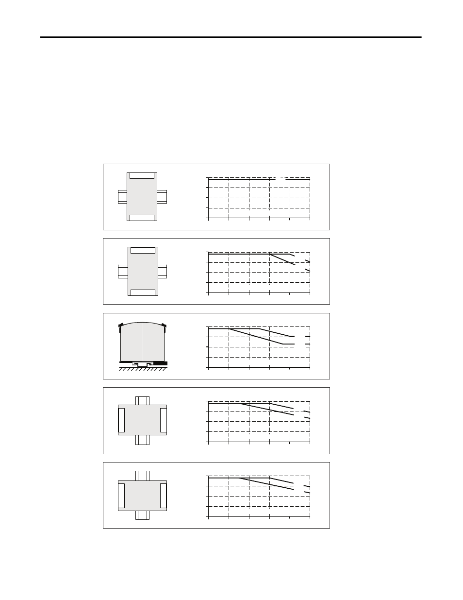
21.11. Mounting Orientations
Mounting orientations other than input terminals on the bottom and output on the top require a reduction in
continuous output power or a limitation in the max. allowed ambient temperature. The amount of reduction
influences the lifetime expectancy of the DC/DC converter. Therefore, two different derating curves for continuous
operation can be found below:
Curve A1 Recommended
output
current.
Curve A2
Max allowed output current (results in approximately half the lifetime expectancy of A1).
Fig. 21-4
Mounting
Orientation A
(Standard
orientation)
DC/DC
Converter
OUTPUT
Output Current
0
INPUT
20
30
40
50
70°C
2
3
4A
60
A1
Ambient Temperature
1
Fig. 21-5
Mounting
Orientation B
(Upside down)
DC/D
C
Co
nverter
OUTPUT
INPUT
Output Current
0
20
30
40
50
70°C
2
3
4A
60
Ambient Temperature
1
A2
A1
Fig. 21-6
Mounting
Orientation C
(Table-top
mounting)
Output Current
0
20
30
40
50
70°C
2
3
4A
60
Ambient Temperature
1
A2
A1
Fig. 21-7
Mounting
Orientation D
(Horizontal cw)
DC
/D
C
C
o
nv
erter
OUTPUT
INPUT
Output Current
0
20
30
40
50
70°C
2
3
4A
60
Ambient Temperature
1
A2
A1
Fig. 21-8
Mounting
Orientation E
(Horizontal ccw)
DC
/D
C
C
o
nv
erter
OUTPUT
INPUT
Output Current
0
20
30
40
50
70°C
2
3
4A
60
Ambient Temperature
1
A2
A1