Peak current capability, Back-feeding loads, Inductive and capacitive loads – Rockwell Automation 1606-XLDC92D Power Supply Reference Manual User Manual
Page 17
All parameters are specified at 24V, 3.8A, 24Vdc input voltage, 25°C ambient and after a 5 minutes run-in time, unless noted otherwise.
Rockwell Automation Publication 1606-RM023A-EN-P — January 2014
17
Bulletin 1606 Switched Mode Power Supplies
21. Application Notes
21.1. Peak Current Capability
Solenoids, contactors and pneumatic modules often have a steady state coil and a pick-up coil. The inrush current
demand of the pick-up coil is several times higher than the steady-state current and usually exceeds the nominal
output current. The same situation applies, when starting a capacitive load.
Branch circuits are often protected with circuit breakers or fuses. In case of a short or an overload in the branch circuit,
the fuse needs a certain amount of over-current to trip or to blow. The peak current capability ensures the safe
operation of subsequent circuit breakers.
Assuming the input voltage is turned on before such an event, the built-in large sized output capacitors inside the
DC/DC converter can deliver extra current. Discharging this capacitor causes a voltage dip on the output. The following
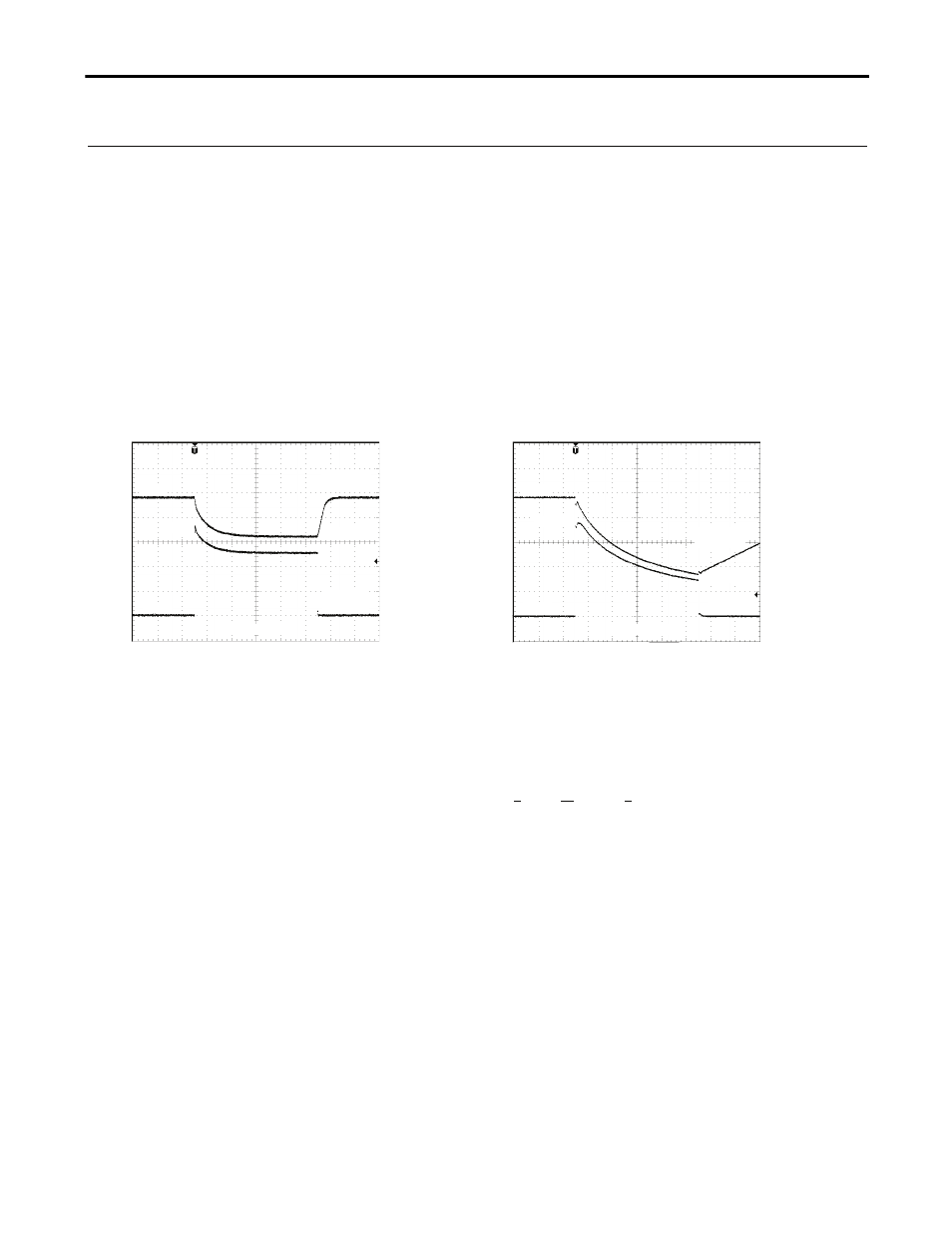
examples show typical voltage dips:
Fig. 21-1 Peak loading with 2x the nominal
current for 50ms, typ.
Fig. 21-2 Peak loading with 5x the nominal
current for 5ms, typ.
Output
Voltage
24V
10ms/DIV
Output
Current
7.6A
16V
24V
Output
Voltage
Output
Current
0A
0A
1ms/DIV
19A
8.5V
Peak load 7.6A (resistive load) for 50ms
Output voltage dips from 24V to 16V.
Peak load 19A (resistive load) for 5ms
Output voltage dips from 24V to 8.5V.
21.2. Back-feeding Loads
Loads such as decelerating motors and inductors can feed voltage back to the DC/DC converter. This feature is also
called return voltage immunity or resistance against Back- E.M.F. (Electro Magnetic Force).
This DC/DC converter is resistant and does not show malfunctioning when a load feeds back voltage to the DC/DC
converter. It does not matter, whether the DC/DC converter is on or off.
The maximum allowed feed-back-voltage is 30Vdc. The absorbing energy can be calculated according to the built-in
large sized output capacitance which is specified in section 5.
21.3. Inductive and Capacitive Loads
The unit is designed to supply any kind of loads, including unlimited capacitive and inductive loads.