Power cable wiring, Important, Attention – Rockwell Automation 1326-xxxx Cable Bulkhead Connector User Manual
Page 4
Publication 1326-IN025B-EN-P - May 2007
4 Bulkhead Connections for Series B 1326 Cables
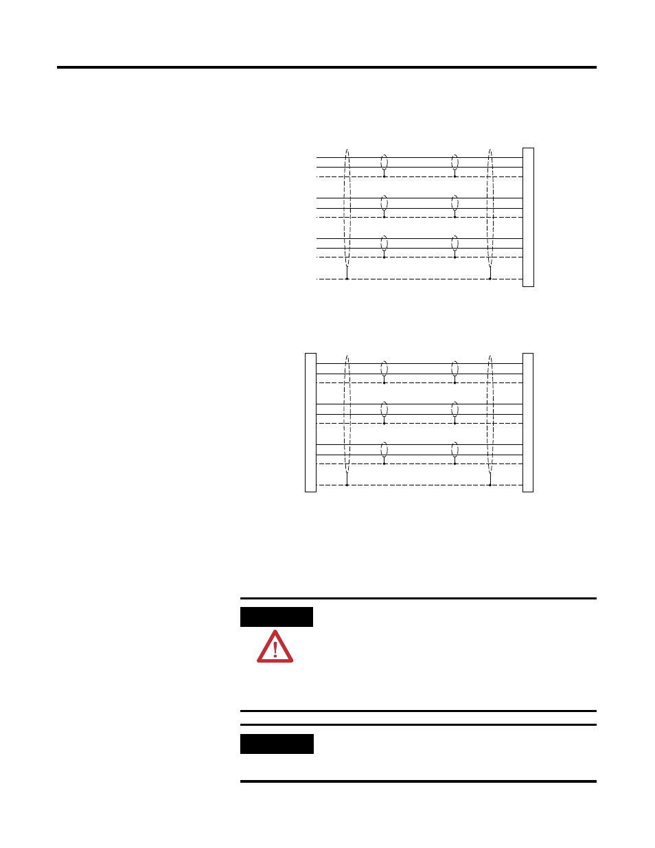
1326-CCU-EL-xxx Cable Wiring Diagram
1326-CCUT-EE-xxx Cable Wiring Diagram
Power Cable Wiring
Connector wiring pinouts and diagrams are provided for the
1326-CPB1x-Dx and 1326-CC1x-Ex power cables. Refer to page 2 for
feedback cable information, and page 8 for installation instructions.
Pair #1: Black
Pair #1: White
Shield
Pair #2: Black
Pair #2: Red
Shield
Pair #3: Black
Pair #3: Green
Shield
Shield
A
B
C
D
E
F
H
G
I
J
Female
Connector
Contact
Bulkhead
Pair #1: Black
Pair #1: White
Shield
Pair #2: Black
Pair #2: Red
Shield
Pair #3: Black
Pair #3: Green
Shield
Shield
A
B
C
D
E
F
H
G
I
J
A
B
C
D
E
F
H
G
I
J
Male
Connector
Pin
Bulkhead
Female
Connector
Contact
Bulkhead
ATTENTION
The dc bus capacitors in a drive retain hazardous voltages after
input power has been removed. Before beginning work on the
output power cable from any drive system, measure the bus
voltage at the drive to verify it has reached a safe level or wait
the full time interval indicated in the warning label on the front
of the drive. Failure to observe this precaution could result in
severe bodily injury or loss of life.
IMPORTANT
Do not coil a power cable on itself. Heat may buildup in a
closely coiled power cable and result in degradation of the
cable insulation.