Network identification of powermonitor w250, Modbus communication reference – Rockwell Automation 1425 PowerMonitor Wireless 250 User Manual
Page 49
Rockwell Automation Publication 1425-UM001A-EN-P - January 2012
49
Software Interface
Chapter 3
Network Identification of PowerMonitor W250
Each of the PowerMonitor W250 units has a unique 16-bit Device ID, which is
printed on the label in the form of [High Byte].[Low Byte].
The low byte of the Device ID is the device Modbus address.
Modbus Communication Reference
The PowerMonitor W250 units are seen as Modbus slaves through the PC
Receiver. The maximum size of a Modbus RTU frame is 256 bytes. A Modbus
request has the following general format.
Read Holding Registers (Function code 0x03)
The following is a Modbus master read request packet. A request is referred to as
a packet sent from the Modbus master application to the gateway slave. This has a
function code value of 0x03, Read Holding Registers.
The Request Data includes a 2-byte starting address offset value and a 2-byte
length value specifying the length of data to be returned in a 16-bit word
(number of Holding Registers, 1…125 (0x7D).
Examples
Read the frequency from the PowerMonitor W250 with Modbus address 63:
• Modbus address - 0x3F
• Starting register - 0x1B (register 27 decimal)
• Length - 0x01
[3F 03 00 1B 00 01 F0 D3]
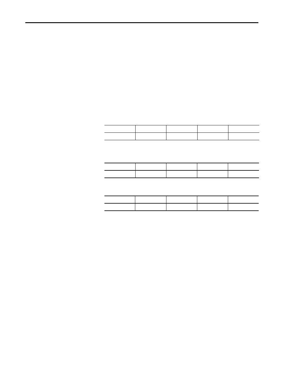
Table 27 - Modbus Request Format
Description
Slave Address
Function Code
Request Data
CRC
Byte Count
1
1
4 (typical, see below) 2 (LSB | MSB)
Table 28 - Master Request Format
Description
Slave Address
Function Code
Request Data
CRC
Hex
0xID
0x03
0xXX …0x7D
0xLSB 0xMSB
Table 29 - Slave Request Format
Description
Slave Address
Function Code
Request Data
CRC
Hex
0xID
0x03
0xXX 0xYY
0xLSB 0xMSB