Rockwell Automation 1503FC IntelliVAC Contactor Control Module - Series E User Manual
Page 21
3-8
Installation and Wiring
1503-UM053B-EN-P – June 2013
Connections
There are three green connectors on the IntelliVAC module for
connections to the control circuitry. Connector plugs are provided with
the module. If additional plugs are required, refer to Chapter 6,
Spare
parts.
Control Power
The IntelliVAC can accept either AC or DC control power. Refer to
Table 1.A for acceptable input power and control signal ratings.
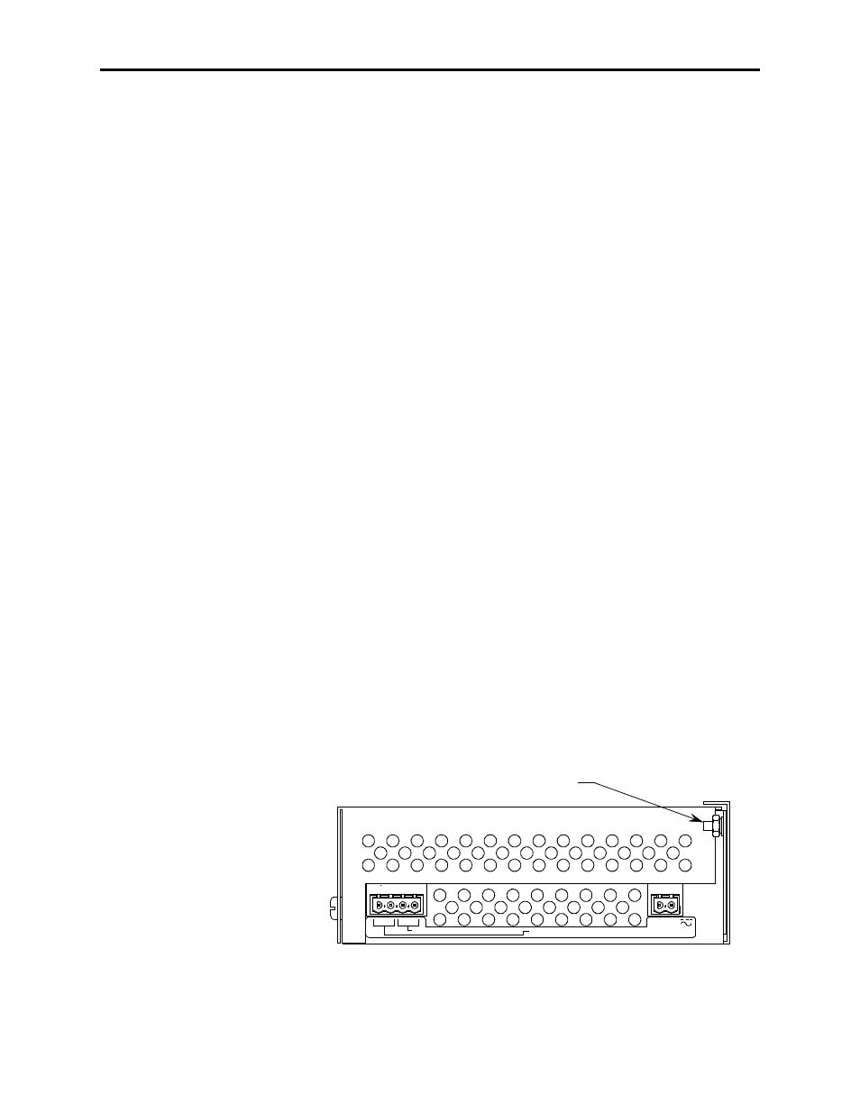
Control power is applied to the module with a two-pole connector
located at the bottom rear portion of the module. Refer to Figure 3.4 for
connections. The ‘L1’ connection is intended to be the ‘Hot’ or ‘+’ side
of the control power, and the ‘L2/N’ connection is intended to be the
‘Neutral’, ‘Return’, or ‘-’ side of the control power.
Status Relays
Status relay connections are accessed with a four-pole connector located
at the bottom front portion of the module. Refer to Figure 3.4 for
connections. There are two status relays, each with one normally-open
contact:
Module Status:
Terminals 13 and 14
Contactor Status:
Terminals 15 and 16
Refer to Chapter 5
Monitoring and Troubleshooting for a description of
operation for the relays.
Refer to Table 1.A for electrical ratings of the status relays.
L2/N
L1
CONTACTOR STATUS OUTPUT (N.O.)
MODULE STATUS OUTPUT (N.O.)
POWER INPUT
13 14 15 16
Ground Connection
Figure 3.4 – Bottom side connections