Power losses – Rockwell Automation 1606-XLSRED80 Power Supply Reference Manual User Manual
Page 5
All parameters are specified at 24V, 80A output current, 25ªC ambient and after a 5 minutes run-in time, unless noted otherwise.
Rockwell Automation Publication 1606-RM011A-EN-P — February 2014
5
Bulletin 1606 Switched Mode Power Supplies
4. Power Losses
DC 24V
Power losses
typ.
2.7W input:
2x20A
typ.
8.3W
input: 2x40A
typ.
3.6W input:
1x40A,
(only one input is connected to input voltage)
Standby power losses
typ.
0.35W
at no output current,
(only one input is connected to input voltage)
typ.
0.7W
at no output current,
(both inputs are connected to input voltages)
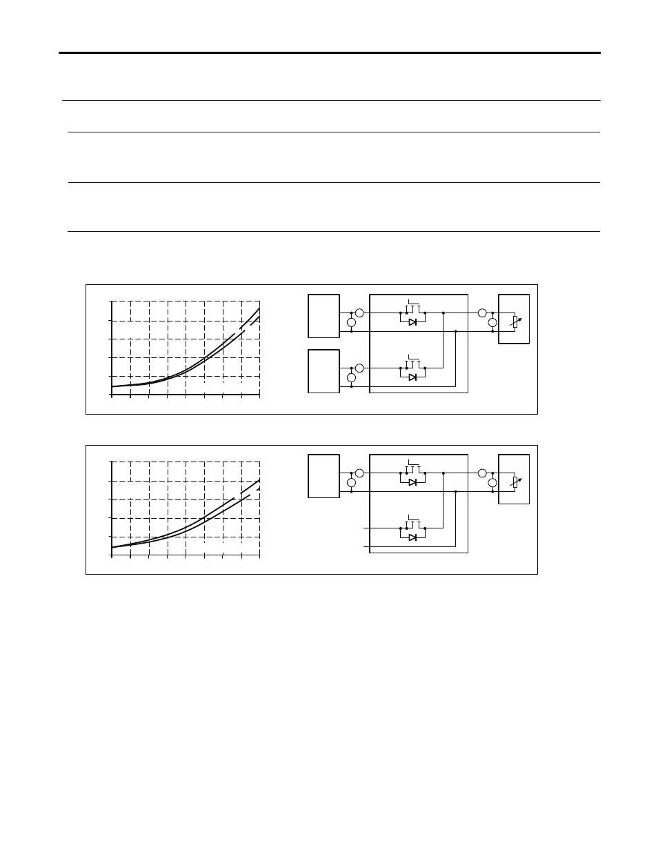
Fig. 4-1 Power losses when both inputs draw equal current
(typical n+1 or 1+1 redundant case, when the power supplies are set into “parallel use” mode)
Power Losses, typ.
0
0
10
20
60
2
4
6
8
10W
80A
50
30
40
70
Output Current
A... 25°C
B... 60°C
A
B
Output
V
A
24V,40A
+
-
"Parallel
Use"
V
A
I
1
I
2
U
1
U
2
A
V
I
OUT
U
OUT
I
1
I
2
=
U
2
U
1
L
=
osses
U
1
=
U
OUT
-
*
I
1
+
)
(
*
U
2
*
I
2
I
OUT
24V,40A
+
-
"Parallel
Use"
Variable
Load,
0-80A
XLSRED80
Input 1
Input 2
Output
Fig. 4-2 Power losses when only one input is used
Power Losses, typ.
0
0
5
10
30
1
2
3
4
5W
40A
25
15
20
35
Output Current
A... 25°C
B... 60°C
A
B
Losses
U
1
=
U
OUT
-
*
I
1
*
I
OUT
Output
V
A
24V,40A
+
-
I
1
U
1
A
V
I
OUT
U
OUT
XLSRED80
Input 1
Input 2
Output
Variable
Load,
0-40A
Note: As soon as voltage is applied on input 2, an additional 0.35W will be consumed. It does not matter whether this channel
contributes to the output current or not.