Rockwell Automation 1492 1771-to-1756 I/O Swing-arm Conversion System User Manual
Page 9
(9)
NOTICE
II. Conversion Steps
d) After the cable is attached to the conversion module, gently lay the opposite end (ControlLogix terminal block) below the module.
e) Repeat steps 5a through 5c and 6a through 6d for the remaining conversion modules.
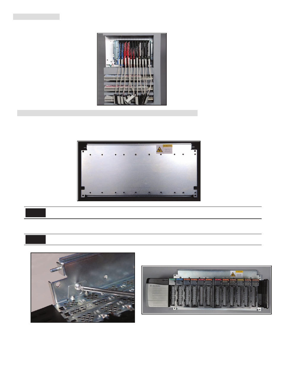
7) Install the 1756 Chassis, I/O Modules and Power Supply on the Conversion Cover-plate
The conversion system installation will be faster if it is possible (depends on space available above the base-plate, refer to next step) to attach the
1756 chassis with its integrated components (I/O modules, power supply, etc) to the conversion system cover-plate, before the cover-plate is
attached to the base-plate. Use the following procedure:
a) Place the cover-plate on a horizontal surface (e.g. table, floor, etc.). Refer to Figure 7a
b) Refer to Figure 7b and 7c, Using the M5 size screws shipped with the cover-plate and base-plate assembly attach the correct 1756 Chassis to
the conversion system cover plate. Torque screws to 2 Nm. Select the appropriate 1756 I/O modules (refer to Appendix B) and power supply.
NOTICE
The decision to install the appropriate 1756 chassis to the cover-plate before or after it is attached to the base-plate is up to the installer. For
proper power supply sizing, refer to the 1756 Power Supply Installation manual available with the product or at www.ab.com/literature.
Before attaching the 1756 I/O Chassis to the conversion cover-plate, closely review and follow the Chassis mounting and system GROUNDING
directions in the 1756 Chassis Installation Instruction manual (1756-IN080x-EN-P) that shipped with the 1756 Chassis or at www.ab.com/literature.
10000060110 (Version 00)
Figure 6e
Figure 7b
Figure 7c
Figure 7a