Rockwell Automation 1492 1771-to-1756 I/O Swing-arm Conversion System User Manual
Page 15
(15)
10000060110 (Version 00)
1771 Analog I/O Module
1
4
9
2
-C
M
1
7
7
1
-L
A
0
0
1
1
4
9
2
-C
M
1
7
7
1
-L
A
0
0
2
1
4
9
2
-C
M
1
7
7
1
-L
A
0
0
3
1
4
9
2
-C
M
1
7
7
1
-L
A
0
0
4
F
u
tu
re
F
u
tu
re
F
u
tu
re
F
u
tu
re
F
u
tu
re
F
u
tu
re
1771-IFE (S-ended voltage)
A
1756-IF16 (S-ended voltage)
1771-IFE (S-ended current)
B
1756-IF16 (S-ended current)
C
D
1771-OFE1
E
1756-OF6VI
1771-OFE2
E
1756-OF6CI
1771-IR
F
1756-IR6I
Cat. Numbers: 1492 Converter for 1771-to-1756 Analog
I/O
Compatible
1756 Analog
I/O Module
1771-IFE (Diff. voltage)
1756-IF16 (Diff. voltage)
1771-IFE (Diff. current)
1756-IF16 (Diff. current)
Appendix C
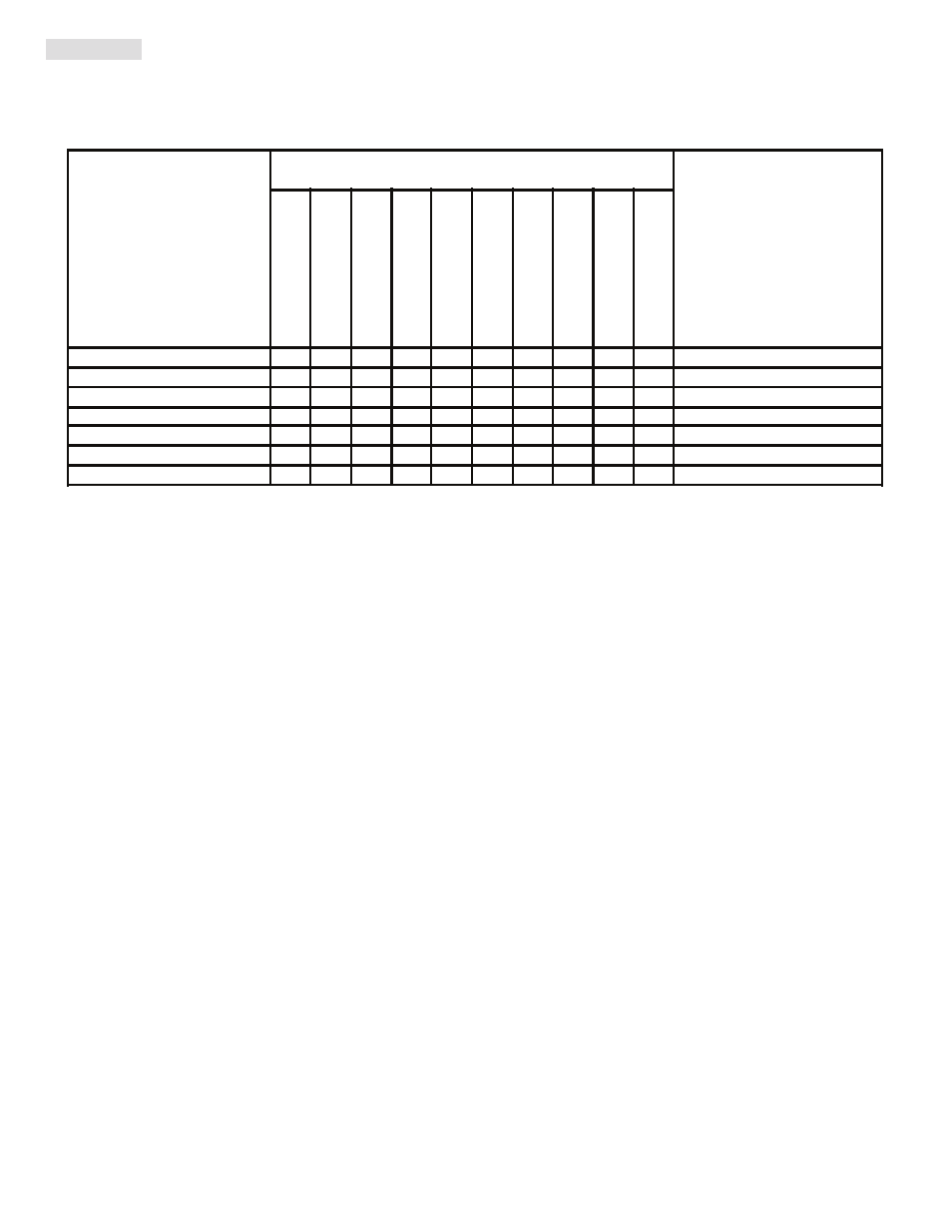
Selection Table for 1771-to-1756 Analog I/O Swing-Arm Converter Module and Pre-Wired Cable
How To Use Matrix A) In the left most column, find the catalog number of the 1771 analog I/O module.
B) Follow that row to the right most column to find the compatible 1756 I/O module.
Review the matrix carefully and review the I/O module Installation Manuals with attention to the
specifications to determine full compatibility.
C) Find the column in the row you selected that contains a capital letter (e.g. A). The catalog number of the
1492 1771-to-1756 Converter is listed at the top of that column. The capital letter from the row and
column intersection indicates the last character of the catalog number for the 1492 cable that connects from
the converter module to the 1756 I/O module (right most column). The FULL cable catalog number is
1492-CONACAB
x, where x is the above letter.
Footnotes:
Three digit number to indicates cable length in meters and tenths of meters (005=0.5 meters).
Available lengths = 1.0 (010) and 0.5 (005) meters.
To understand any issues concerning I/O module compatibility refer to the conversion module wiring
diagrams and the specific I/O module's Installation Manual especially the specification and wiring
instruction sections.
Figure 8a
Figure 8b
Figure 9a
Figure 9b
Figure 9c
Figure 6e
Figure 7b
Figure 7c
Figure 8c
Figure 7a
Base-plate slot
Cover-plate
hinge
Figure 9d
Figure 9e