Grounding, Drive – Rockwell Automation 1329L AC Induction Motors User Manual User Manual
Page 9
AC Induction Motors
9
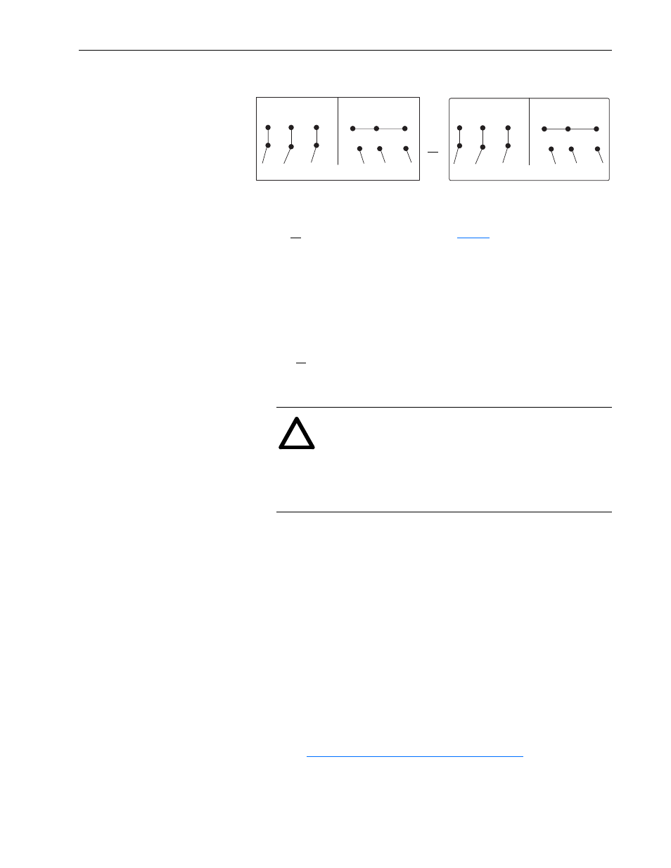
Procedure:
1. Connect for low or high voltage as shown.
2. Check that the direction of air flow is in agreement with the
“direction of air flow” arrows mounted on the motor. If
directional flow is incorrect, interchange power leads to T1 & T2
or U1 & V1.
Grounding
The user is responsible for assuring that the grounding method is in
accordance with the National Electric Code and the applicable local
codes. The ground connection should be a solid and permanent
metallic connection between the ground point, the motor terminal
housing and the motor frame. A ground lead is provided inside the
terminal box.
Due to the need to carry higher frequency ground currents (from
switch voltage waveforms) the ground connection/path must be low
impedance/low resistance. Such ground currents exist during normal
operation on inverter power.
Drive
L180-L320 frame motors are supplied with a shaft suitable for a belt
or coupled drive.
Belt loads should be checked against maximum allowable radial loads
under
“Shaft Loads - Axial and Radial” on page 13
Bradley to determine L440 frame belt load requirements.
Frames L360S and L400S are suitable for coupled duty only, larger
shafts are supplied for belted duty.
(Delta)
(Star)
T6
T4
T5
T6
T4
T5
T1
T2
T3
L1
L2
L3
T1
T2
T3
L1
L2
L3
Low Volts
Line
High Volts
(Delta)
(Star)
W2
U1 = Black
U2 = Green
V1 = Blue
V2 = White
W1 = Brown
W2 = Yellow
U2
V2
W2
U2
V2
U1
V1
W1
L1
L2
L3
U1
V1
W1
L1
L2
L3
Low Volts
Line
High Volts
or
or Connection Diagram shown on
.
!
ATTENTION: Connect an appropriate equipment
grounding conductor to the drive ground terminal, motor
frame, transformer enclosure (if used), drive electrical
enclosure and an appropriate grounding electrode. Failure
to observe these precautions could result in personal injury
and/or death.