Shipping blocks, Encoder connection diagrams – Rockwell Automation 1329L AC Induction Motors User Manual User Manual
Page 10
10
AC Induction Motors
Proper alignment is a key step for long life of bearings, shafts and
belts, and minimum downtime. Misalignment can cause excessive
vibration and damaging forces on shaft and bearings. For direct
coupled drives, flexible couplings facilitate alignment. For belt drives,
the sheave must be placed as close as possible to the motor bracket.
Shipping Blocks
Motors supplied with roller bearings at the drive end are shipped with
wooden blocking to prevent axial movement of the shaft during
shipment. Remove the blocking and bolts securing it and discard.
Make sure motor shafts turn freely. If motor is to be reshipped,
blocking of bearing is required.
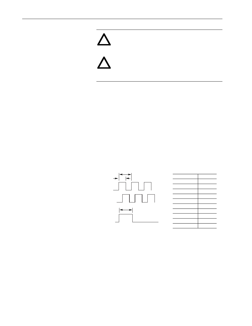
Encoder Connection Diagrams
Dynapar H20 – 10 pin M/S Connector
Lakeshore – Epic Connector or Plain Cable
The following table is a universal wiring guide for the latching Epic
connector or plain cable. Wires that are not used should be left not
connected (never connect to power or common). For optimum EMI
noise immunity, connect the encoder shield (pin 10 or braid) to the
cable shield. The encoder shield is internally isolated from the
encoder frame. The cable shield should still be connected to ground at
the receiving end. This encoder has a line driver output. A pull-up
resistor is not required.
!
ATTENTION: Incorrect motor rotation may cause
personal injury or damage the equipment. Check direction
of motor rotation before coupling motor to load.
!
ATTENTION: Ensure that all guards are properly installed
before proceeding. Exercise extreme care to avoid
contacting rotating parts. Failure to observe these
precautions could result in personal injury.
Output A
90
° ±45°
360
°
Output B
Index
Electrical
Output waveform
CCW Rotation of Shaft
360
° ±180°
Output Terminations
Signal
Pin
Output A
A
Output B
B
Output Z
C
Vcc
D
Common
F
Case
G
No Connection
E
Output A (NOT)
H
Output B (NOT)
I
Output Z (NOT)
J