Connections – Rockwell Automation 1329L AC Induction Motors User Manual User Manual
Page 7
AC Induction Motors
7
Connections
Bypass Mode
If the motor is to be used in bypass mode, the user must select a motor
starter and overcurrent protection suitable for this motor and its
application. Consult motor starter application data as well as the
National Electric Code and/or other applicable local codes. Contact
Allen-Bradley to determine suitability of motor for specific
applications in bypass mode.
Power Wiring
Single Voltage Motors – On Single voltage, three lead motors,
connect leads marked U/T1, V/T2, W/T3, to the appropriate drive
output terminals. Refer to the Drive User Manual for further
information.
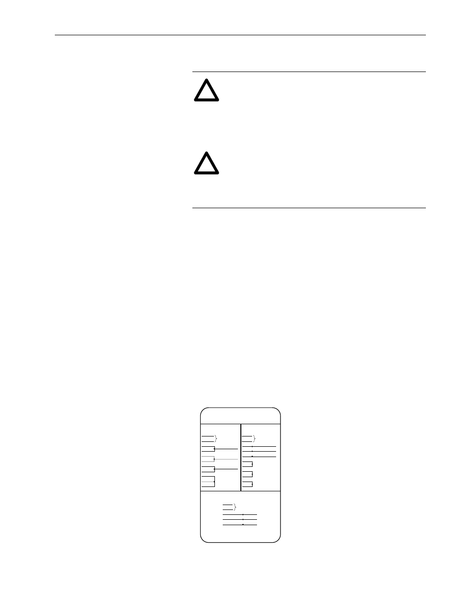
Dual Voltage Motors – Be sure the motor leads are connected
properly for the desired “Low” or “High” voltage connection per the
motor connection diagram (see below). Refer to the Drive User
Manual for proper drive output connections.
!
ATTENTION: The user is responsible for conforming with
the National Electrical Code and all other applicable local
codes. Wiring practices, grounding, disconnects and
overcurrent protection are of particular importance. Failure
to observe these precautions could result in severe bodily
injury or loss of life.
!
ATTENTION: This equipment is at line voltage when AC
power is connected. Disconnect and lockout all ungrounded
conductors of the power line. Failure to observe these
precautions could result in personal injury and/or loss of
life.
3 PHASE-DUAL VOLTAGE
LOW VOLTAGE
THERMOSTAT
LEADS
L1
P1
P2
U/T1
T7
V/T2
T8
W/T3
T9
T4
T5
T6
THERMOSTAT
LEADS
HIGH VOLTAGE
L2
L3
L1
P1
P2
U/T1
V/T2
W/T3
T4
T7
T5
T8
T6
T9
L2
L3
P1
P2
U/T1
V/T2
W/T3
L1
L2
L3
3 PHASE-SINGLE VOLTAGE
THERMOSTAT
LEADS