Rockwell Automation 500LG Lighting Contactor Instruction Manual User Manual
Page 9
Installing Bulletin 500LC Lighting Contactors
9
Publication 500LC–IN001A–EN–P May 2005
Solid–state Control Modules – Field Installed Modifications
500LC–47CM*, 500LC–48CM*, 500LC–49SS*
These control modules are to be connected and mounted on the bottom or
right side of the Bulletin 500LC Lighting Contactor depending on the
number of 500LC poles or N/O and N/C contact configuration. A control
module can be field installed by ordering the appropriate module kit. Refer
to wiring diagrams on page 13 or 14.
Operation
Mod. 500LC–47CM*
control modules are for two–wire control of the
Bulletin 500LC only. The module must be energized to close the 500LC, and
de–energized to open the 500LC. Therefore, use a single pole, maintained
type control station to operate the control module.
Mod. 500LC–48CM*
control modules are for three–wire control of the
Bulletin 500LC. One terminal must be energized to close the 500LC; another
terminal must be energized to open the 500LC. If neither or both terminals
are energized, no output will occur. Therefore, use a single pole, double
throw, momentary type control station to operate the control module.
Mod. 500LC–49SS*
control modules are for Form 3 (start–stop) control of
the Bulletin 500LC. The modules must be energized to close the 500LC, and
de–energized to open the 500LC. Therefore, use one normally–closed and
one normally–open separate control stations to operate the control module.
There are four different control modules for each Mod. 500LC–47CM*,
500LC–48CM*, and 500LC–49SS*. Each module is suitable only for the
control voltage marked on it. Refer to Table F. Ratings for the control
modules are listed in Table H.
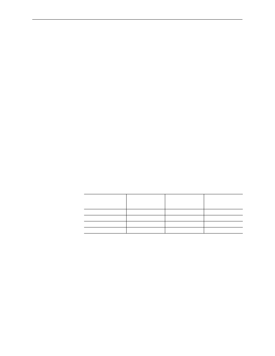
Table F – Solid–State Control Module numbers
Module Control
Voltage
2–Wire Control
Modules
3–Wire Control
Modules
Form 3 Control
Modules
120V AC
500LC–47CM120
500LC–48CM120
500LC–49SS120
24V AC & DC
500LC–47CM24
500LC–48CM24
500LC–49SS24
240 / 277V AC
500LC–47CM240
500LC–48CM240
500LC–49SS240
12V AC & DC
500LC–47CM12
500LC–48CM12
500LC–49SS12
Connections
Connections to the Mod. 500LC–47CM*, 500LC–48CM*, and
500LC–49SS* control modules are shown in Table G. Also refer to the labels
in Figure 1 and to wiring diagram on page 13 or 14. Barrier screw type
terminals accept #22–12 AWG Cu control wiring. Tighten terminals to 12
inch–pounds.
The control modules have two colored leads preconnected to the O and C
terminal bus on the 500LC. A yellow wire runs between the O terminals; and
orange/black wire runs between the C terminals.
Connect your control wiring for the module to terminals 2, 3, and 4 on the
modules. Terminal 2 is not used on Mod. 500LC–47CM* and terminal 1 is
never used.
Connect your control wiring for the 500LC Lighting Contactor (coil voltage)
to terminal 5 on the control module and terminal L on the500LC. If the line
voltage (service) is the same as the coil voltage, the control voltage can some
directly from the poles of the 500LC Lighting Contactor.