Rockwell Automation 500LG Lighting Contactor (Mechanically and Electrically Held) User Manual
Cat 500lg_), Mounting position, Warning
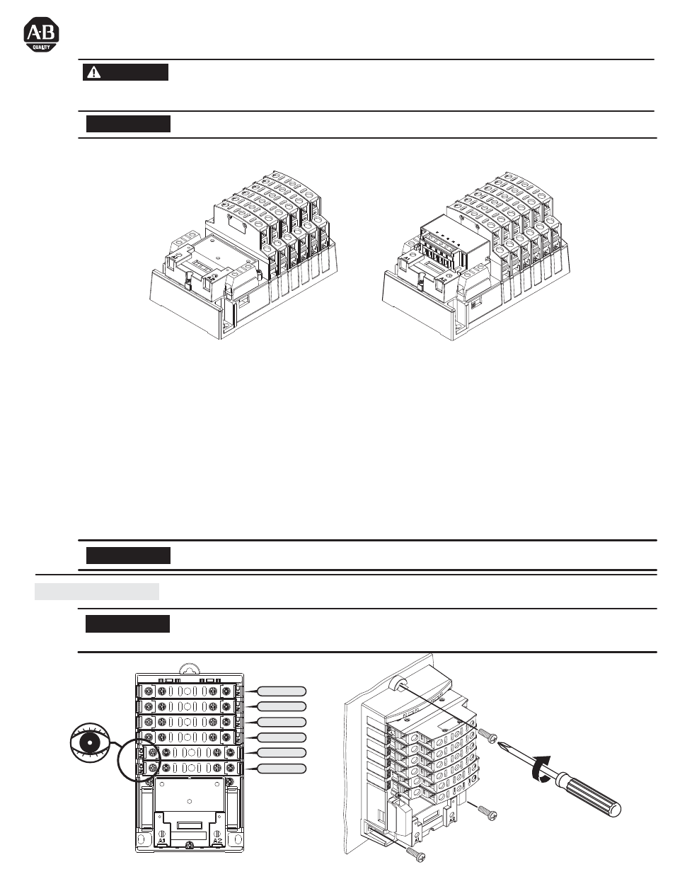
Mount lighting contactor in the vertical position only as shown below.
A maximum of 12 poles may be installed on the base. Positions "1" thru "4" on the base may be configured as either
normally open "N.O." or normally closed "N.C.", while positions "5" and "6" may be configured as "N.O." only.
Lighting Contactor (Mechanically and Electrically Held)
(Cat 500LG_)
Mounting Position
Figure 1: Electrically-Held
Figure 2: Mechanically-Held
500LG
To prevent electrical shock, disconnect from power source before installing or servicing. Follow NFPA 70E requirements.
Install in a suitable enclosure. Keep free from contaminants.
Bulletin 500LG lighting contactor installation must be performed by a "Qualified Person" as defined by the National
Electrical Code.
WARNING
Position "1"
Position "2"
Position "3"
Position "4"
Position "5"
Position "6"
500LG
NOTICE
The control module is available up to 277V maximum. For control voltage greater than 277V, use a control transformer.
NOTICE
To prevent malfunction or shortened life, protect the 500LG lighting contactor from construction grit and metal chips.
NOTICE
The Bulletin 500LG lighting contactor is available in either electrically-held (Figure 1) or mechanically-held (Figure 2) configurations.
Main Base
The base of the lighting contactor has provisions to accept up to 12 power poles where 12 N.O. contacts are possible or any
combinations of N.O. and N.C. Positions 1 through 4 on the base can be configured to either normally open (N.O.) or normally closed
(N.C.) while positions 5 and 6 can only be configured as normally open (N.O.).
Power Pole
Power poles are available in either single pole (500LG-1PCK) or double poles (500LG-2PCK).
Auxiliary Contact
The auxiliary contact blocks are available in either single pole (500LG-141C) or double poles (500LG-142C) contact. Auxiliary contact
can be installed on either side of the base. When installed on the RIGHT side, the auxiliary contact functions as a N.C. contact. When
installed on the LEFT side, the auxiliary contact functions as a N.O. contact.
Control Module Kits
Control module kits enable conversion of an electrically held contactor to a mechanically held contactor. These kits are available in either
2-wire or 3-wire control versions in a variety of voltages. See renewal parts section (page 5) for catalog number.
500LG
10 - 15 lb-in
10 - 15 lb-in