Special features, Customer configurations, Applications – Rockwell Automation 440R MSR42 Control Module User Manual User Manual
Page 4: Typical applications, Application restrictions, Dimensions, Wiring diagrams, Basic configuration, Original instructions
2
Light Curtain Multi-Function Control Module User Manual
Original instructions
Up to three expander modules can be easy attached & controlled by the
base module.
In addition to the multifunction controllers, models are offered in special
configurations which are described in the appendix at the end of this
manual.
Special features
The characteristics of the MSR42 base module:
• Category 4, PLe according to EN ISO 13849-1
• Type 4 according to EN61496-1 / -2
• SIL CL3 according to EN62061
• SIL3 based on IEC 61508
• Short response times
• Expandable
• Up to 3 safety relay expander modules per base module
• Adjustable stop delay time
• Different safety components suitable for connection
• Blanking
• Muting
• Single scan selectable
Customer Configurations
The configuration of a MSR42 base module may very easily be adapted
to the customer requirements of an individual application with the help
of the USB/optical interface and the Allen-Bradley Guardmaster
Software “Configuration & Diagnostic Tool”. More information can be
found in the Software Technical Manual. The software is capable of
generating a configuration control document which lists configurations
and specifications of the controller and light curtain (Figure 16).
Applications
Typical applications
Typical MSR42 base module applications are:
• Presses
• Robotic cells with automatic insertion
• Assembly lines
• Indexing tables
• Conveyor systems
• Automatic storage facilities
Application restrictions
MSR42 base modules are not intended for application in explosive (EX)
or in radioactive environments.
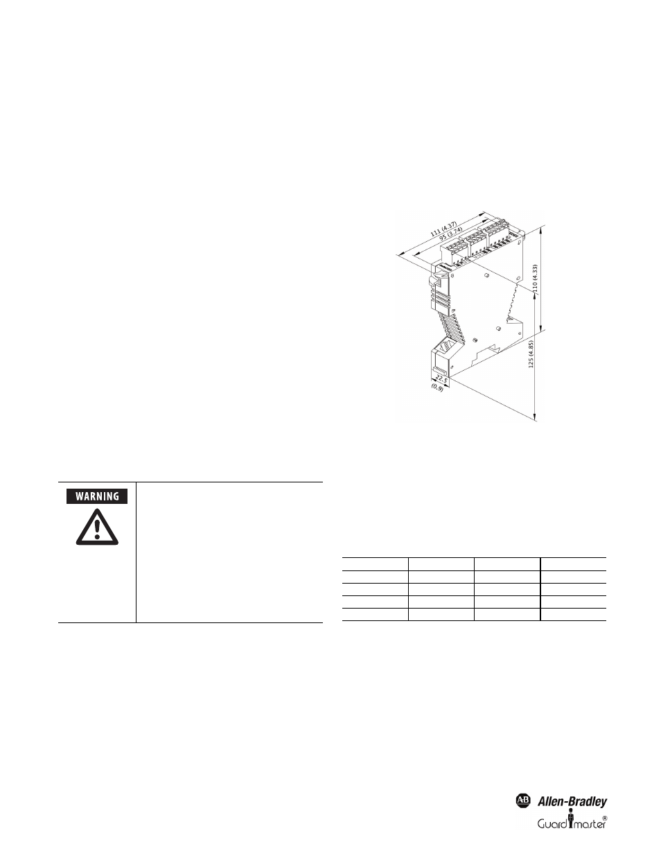
Dimensions
The dimensions of the MSR42 housing are illustrated in Figure 2.
Figure 2: Base module dimensions are the same for expansion modules
Wiring diagrams
Basic configuration
The following figures show the connection possibilities for the MSR42
base module with the basic configuration. The logic of this basic version
is exemplified in the accompanying configuration control document:
The resolution and the response time may
increase due downloading other
configuration settings for the Micro 400
and other safety sensors connected to
MSR42. Consider the relevant resolution
and the maximum response time when
evaluating the safety distance. See
Chapter 7. All relevant data of the actual
configuration are always described in the
actual configuration control document
for that controller. Make sure that the
actual document is always stored near to
the control unit.
Figure
Safety component
Start mode
Start release
Figure 3
Micro400
manual
no
Figure 4
Micro400
manual
yes
Figure 5
Micro400
automatic
no
Figure 6
Micro400
automatic
yes