Cefb1-12, English deutsch français italiano español – Rockwell Automation 193-EIMD Electronic Motor Protection Relay User Manual
Page 13
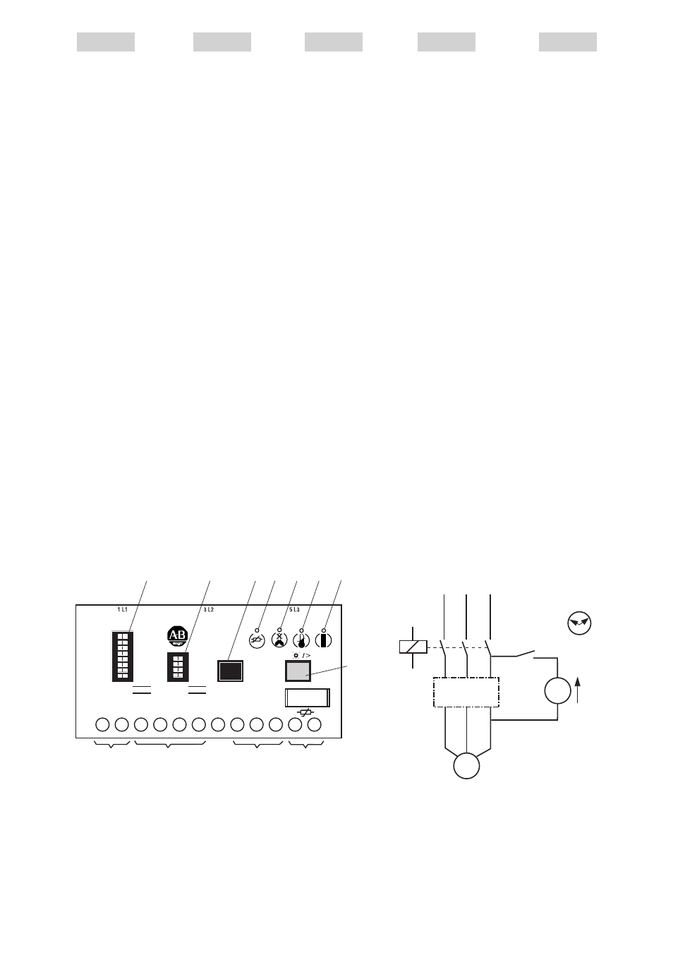
7.2 Tests del funcionamiento
a) Cierre el interruptor S1 y
ponga simultáneamente
en marcha el cronómetro
P1T. Transcurridos 1,5
segundos, dispara la
protección contra cortes
de fase: se enciende su
LED rojo (Fig. 10, H),
simultáneamente vuelve
al reposo el relé de salida
y se apaga el LED verde
(Fig. 10, F).
En el CEFB1-12,
CEFB1-22, CEFB1-42 y
CEFB1-52 intermite el
LED rojo (Fig. 10, G) de
la protección contra
sobrecargas térmicas
(se indica sobrecorriente
cuando la corriente del
motor excede el 110 %
de la corriente nominal I
e
ajustada). Transcurrido
el tiempo ajustado
t
6x
I
e
1)
(Fig. 10, K) en el
CEFB1 se enciende
continuamente el LED
rojo (Fig. 10, G): la
protección contra
sobrecargas térmicas ha
provocado el disparo.
b) A continuación, en los
tests de funcionamiento
7.2.a) ponga a cero el
cronómetro P1T. Abra el
interruptor S1 y pogna
simultáneamente en
marcha el cronómetro
P1T. Siguen encendidos
ambos LEDs rojos
(protección contra cortes
de fase Fig. 10, H y
protección contra
sobrecargas térmicas
Fig. 10, G).
7.2 Functional tests
a) Simultaneously close
switch S1 and start
stopwatch P1T. The phase
loss protection trips after
1.5 s: its red LED comes
on (Fig. 10, H) the output
relay drops out and the
green LED (Fig. 10, F)
goes out. With CEFB1-12,
CEFB1-22, CEFB1-42 and
CEFB1-52 the red LED
(Fig. 10, G) of the thermal
overload protection flashes
(overcurrent indication
when the motor current
exceeds 110% of the set
rated current I
e
). After the
time t
6x
I
e
1)
set on the
CEFB1 has elapsed
(Fig. 10, K), the red LED
(Fig. 10, G) goes into a
permanent ON state: the
thermal overload protection
has responded.
b) After conclusion of the
functional test 7.2.a), reset
the stop-watch P1T to zero.
Simultaneously open s
witch S1 and start stop-
watch P1T. Both red
LEDs (phase loss
protection Fig. 10, H and
thermal overload protection
Fig. 10, G) are still on.
7.2 Funktionstests
a) Schalter S1 schliessen
und gleichzeitig Stoppuhr
P1T starten. Nach
1.5 Sekunden löst der
Phasenausfallschutz aus:
dessen rote LED
(Fig. 10, H) leuchtet,
gleichzeitig fällt das
Ausgangsrelais ab und
die grüne LED
(Fig. 10, F) erlischt.
Beim CEFB1-12,
CEFB1-22, CEFB1-42 und
CEFB1-52 blinkt die rote
LED (Fig. 10, G) des
thermischen Überlast-
schutzes (Überstrom-
anzeige, wenn der Motor-
strom 110% des einge-
stellten Nennstroms I
e
überschreitet). Nach
Ablauf der am CEFB1
eingestellten Zeit t
6x
I
e
1)
(Fig. 10, K) leuchtet die
rote LED (Fig. 10, G)
dauernd: der thermische
Überlastschutz hat
ausgelöst.
b) Anschliessend an den
Funktionstests 7.2.a) ist
die Stoppuhr P1T auf
Null zu stellen. Schalter
S1 öffnen und gleich-
zeitig Stoppuhr P1T
starten. Beide rote LED
(Phasenausfallschutz
Fig. 10, H und
thermischer Überlast-
schutz Fig. 10, G)
leuchten weiter.
7.2 Test des fonctions
a) Fermer le commutateur
S1 et simultanément
enclencher le
chronomètre P1T. Aprés
1,5 s la protection contre
les défaillances de phase
déclenche: la diode rouge
correspondante
(Fig. 10, H) s’allume,
le relais de sortie
déclenche et la diode
verte (Fig. 10, F) s’éteint.
Pour le CEFB1-12,
CEFB1-22, CEFB1-42 et
CEFB1-52, la diode rouge
(Fig. 10, G) de la
protection contre les
surcharges thermiques
clignote (Indication de
courant de surcharge, I
e
courant dépasse 110%
du courant nominal régle
Ie). Aprés le temps régle
t
6x
I
e
1)
(Fig. 10, K),
cette même diode
(Fig. 10, G) s’allume en
permanence: la protection
contre le surcharges
thermiques a déclenché.
b) Remettre le chronomètre
P1T à zéro. Ouvrir le
commutateur S1 et
simultanément
enclencher le
chronomètre P1T. Les
deux diodes lumineuses
rouges (Fig. 10, H pour
les défaillances de phase
et Fig. 10, G pour la
surcharge thermique)
restent allumées.
English
Deutsch
Français
Italiano
Español
7.2 Prove delle funzioni
a) Chiudere l’interruttore S1 e
contemporaneamente
mettere in moto il
cronometro P1T. Dopo 1.5
secondi la protezione
contro mancanza di fase
provoca uno sgancio: si
accende il suo LED rosso
(Fig. 10, H),
contemporaneamente
cade il relais d’uscita e si
spegne il LED verde
(Fig. 10, F).
Con CEFB1-12, CEFB1-22,
CEFB1-42 e CEFB1-52
lampeggia il LED rosso
(Fig. 10, G) della
protezione termica di
sovraccarico (indicazione
di sovracorrente, quando
la corrente del motore
oltrepassa il 110% della
corrente nominale
regolata I
e
). Trascorso il
tempo t
6x
I
e
1)
regolato al
CEFB1 (Fig. 10, K) si
accende in permanenza il
LED rosso (Fig. 10, G):
la protezione termica di
sovraccarico ha provocato
uno sgancio.
b) Dopo la prova di funzione
7.2.a), il cronometro deve
essere rimesso a zero.
Aprire l’interruttore S1 e
mettere contemporanea-
mente in moto il
cronometro P1T.
Entrambi i LED rossi
(protezione contro
mancanza di fase Fig. 10,
H e protezione termica
di sovraccarico Fig. 10, G)
continuano ad essere
accesi.
Fig. 13
13
6 x I
e
oder/or/ou/o
2 x I
e
M
S1
L2 L3
1
3
5
CEFB1
F1
M1
A2
A1
K1
G1
P1T
L1
4
2
3
6
5
2
1
3
2 T1 T2 T3
L1 L2 L3
~
3
~
Fig. 10
(-)A2 (+)A1 98
97
96
95
1T2
1T1
Test
6 x
I
e
Reset
+ 1
+ 2
+ 3
+ 5
+10
+20
+40
+80
+20
+ 2
+ 4
+ 8
+16
I
e
(=I
B
) = A
t
6 x Ie
= S
CEFB1-12
L
K
J
I
H
G F
E
A
B
C
D
1
2
3
t°
+