What you need to do, Step 1: remove power from the drive, Step 2: open the drive – Rockwell Automation 20P-RES-A0 PowerFlex DC Drive Resolver Feedback Option Module User Manual
Page 2
2
Rockwell Automation Publication 20P-IN071B-EN-P - June 2011
PowerFlex
®
DC Drive Resolver Feedback Option Module
What You Need to Do
To install the resolver feedback option module:
❐ Step 1: Remove power from the drive
❐ Step 2: Open the drive
❐ Step 3: Install the resolver interface board
❐ Step 4: Install the resolver feedback board
❐ Step 5: Wire the resolver interface and feedback boards
❐ Step 6: Replace the protective covers and configure the resolver feedback
option module
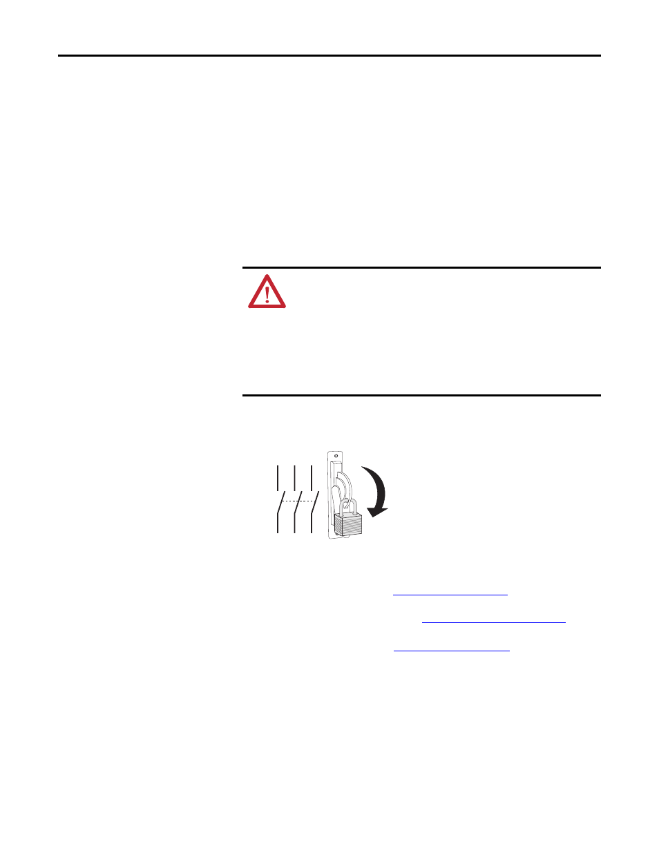
Step 1: Remove Power
from the Drive
• Remove and lock-out all incoming power to the drive.
Step 2: Open the Drive
• To open frame A drives see
.
• To open frame B and C drives see
Frame B and C Drives on page 4
• To open frame D drives see
ATTENTION: Remove power before making or breaking cable
connections. When you remove or insert a cable connector with power
applied, an electrical arc may occur. An electrical arc can cause personal
injury or property damage by:
•
sending an erroneous signal to your system’s field devices, causing
unintended machine motion
•
causing an explosion in a hazardous environment
Electrical arcing causes excessive wear to contacts on both the module
and its mating connector. Worn contacts may create electrical resistance.
L1
L2
L3
O
I