Wiring the resolver feedback board – Rockwell Automation 20P-RES-A0 PowerFlex DC Drive Resolver Feedback Option Module User Manual
Page 14
14
Rockwell Automation Publication 20P-IN071B-EN-P - June 2011
PowerFlex
®
DC Drive Resolver Feedback Option Module
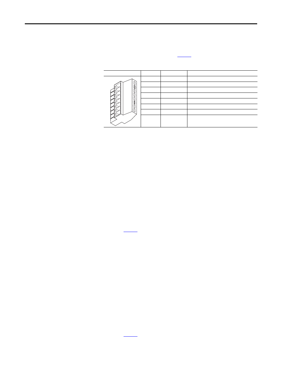
Wiring the Resolver Feedback Board
Terminal block P1 on the resolver feedback option (top) board provides the
connection points for a single resolver.
details the connections.
Table 5 - Resolver Feedback Board P1 Terminal Descriptions
• P1 terminal block part number: 1639300000
• P1 terminal block material number: BL 3.50/08/90F SN BK BX
Recommended Resolver Cable
For the best results, Belden® 9730 (or equivalent) cable is recommended. For
retro-fit applications where Reliance Electric™ resolvers (800123-xxx), wiring
(417900-207CG) or Automax™ systems were used, existing wiring may be used
(assuming it is in good working condition).
Belden 9730 (or Equivalent) Cable Attributes
• 3 twisted pairs, 24 AWG, shielded, -20 to +80 °C, 300V
• Inductance = 0.23
μ
H/ft
• Capacitance = 12.5 pF/ft
• Resistance = 24
Ω
/1000 ft
for maximum cable lengths
Reliance Electric 417900-207CG Cable Attributes
• 3 Twisted Pairs, 18 AWG, unshielded, 80°C, 300V
• Chrome FPR Jacket, Plenum Rated
• Twists Per Inch: 2-3 twists per inch of wire lay per pair
• Inductance per 1000 Feet: 0.13
μ
H ±10% as read on a GEN_RAD Model
1658 RLC Digibridge or equivalent
• Capacitance Per Pair: not to exceed 30 pF/ft ±0.3 pF as read on a
GEN_RAD Model 1658 RLC Digibridge or equivalent
• Capacitance Difference Pair to Pair: not to exceed 0.6 pF/foot as read on a
GEN_RAD Model 1658 RLC Digibridge or equivalent
• Resistance per 1000 Feet: 17.15
Ω
±10%
• Insulation Thickness: 0.008 in.
• Conductor Stranding 16/30
• Jacket Thickness: 0.018 in.
• See
for maximum cable lengths
Terminal
Signal
Description
8
REF HIGH
Positive Reference signal
7
SHIELD
Connection point for resolver cable shield
6
REF LOW
Negative Reference signal
5
SIN HIGH
Positive Sine signal
4
SHIELD
Connection point for resolver cable shield
3
SIN LOW
Negative Sine signal
2
COS HIGH
Positive Cosine signal
1
COS LOW
Negative Cosine signal
12
34
5
6
7
8