Resolver wiring diagrams, Dc drive resolver feedback option module – Rockwell Automation 20P-RES-A0 PowerFlex DC Drive Resolver Feedback Option Module User Manual
Page 16
16
Rockwell Automation Publication 20P-IN071B-EN-P - June 2011
PowerFlex
®
DC Drive Resolver Feedback Option Module
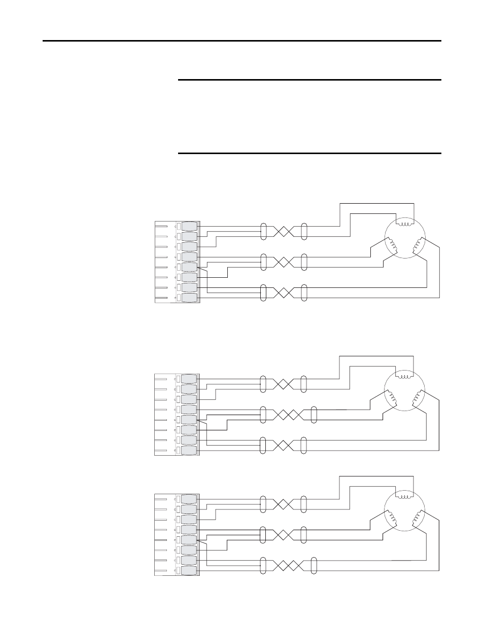
Resolver Wiring Diagrams
Figure 4 - Resolver Interface Connection Example for Clockwise Rotation - Count
Up
Figure 5 - Resolver Interface Connection Examples for Clockwise Rotation - Count
Down
IMPORTANT
The shield connections must only be made at the drive end of the
cable (resolver end of cable shield is unattached) as shown in the
diagrams below. Grounding both ends of the shielded cable can result
in ground loops that could damage the resolver and/or drive.
Also, the resolver connections are considered signal level wiring and
MUST be run separate from control and power wiring (and at least 12
inches apart).
REF HIGH 8
SHIELD 7
REF LOW 6
SIN HIGH 5
SHIELD 4
SIN LOW 3
COS HIGH 2
COS LOW 1
REF
+
-
SIN
COS
+
+
-
-
-
+
-
+
-
+
-
+
-
+
-
+
Terminal Block P1
Resolver
REF HIGH 8
SHIELD 7
REF LOW 6
SIN HIGH 5
SHIELD 4
SIN LOW 3
COS HIGH 2
COS LOW 1
REF
+
-
SIN
COS
+
+
-
-
-
+
-
+
-
+
-
+
+
-
-
+
REF HIGH 8
SHIELD 7
REF LOW 6
SIN HIGH 5
SHIELD 4
SIN LOW 3
COS HIGH 2
COS LOW 1
REF
+
-
SIN
COS
+
+
-
-
-
+
-
+
-
+
+
-
-
+
-
+
Reverse Polarity of Sine
or Cosine Signals
Terminal Block P1
Resolver
- 20P PowerFlex DC Drive - Frame D Bimetal Thermostat (10 pages)
- 1336S_F_T_E_R F Frame Snubber Resistor Repl. (6 pages)
- 22-COMM PowerFlex 4-Class DSI (Drive Serial Interface) Network Communication Adapter (4 pages)
- 8-545 Plug In Solid State Relay (2 pages)
- 20-HIM-B1 PowerFlex 7-Class HIM Bezel (DPI) (4 pages)
- 100 Contactors with DC Coil (1 page)
- 100 Contactors with DC Coil (2 pages)
- 20P PowerFlex DC Drive - Frame D Switching Power Supply Circuit Board (6 pages)
- 140G-MTFx_MTHx_MTIx_MTKx Trip Unit Installation-140G-M (6 pages)
- 45BRD Analog Laser Sensor (4 pages)
- 20D Multi-Device Interface Option Board for PowerFlex 700S Drives (20 pages)
- 56RF RFID 18 mm Cylindrical Transceiver (2 pages)
- 42KC Miniature Rectangular: 5V DC Version (2 pages)
- 20P PowerFlex DC Drive - Frame A Switching Power Supply Circuit Board (16 pages)
- 21P-MISC-A-TP-2 Transition Tube Kit #C19-6/7 For PowerFlex 755 w/OEM Liquid Cooling Fr 6/7 Drive (2 pages)
- 42BT Background Suppression Sensor (3 pages)
- 42CB High Speed 18mm Cylindrical (4 pages)
- 140EX-JE2_JE3 Molded Case Circuit Breaker (4 pages)
- 140G-K-EAM1A Early Make Aux Contact for Rotary Handle Oper Mech-140G-K (3 pages)
- 140G-K-EAM1A Early Make Aux Contact for Rotary Handle Oper Mech-140G-K (1 page)
- 20-HIM-A6 PowerFlex (Human Interface Module) (74 pages)
- 42CF General Purpose 12mm Cylindrical (4 pages)
- 20D PowerFlex 700S Phase II Drive Frames 1...6 (80 pages)
- 140EX-HE1_HE2 Molded Case Circuit Breaker (4 pages)
- 140EX-HE1_HE2 Molded Case Circuit Breaker (6 pages)
- 20B PowerFlex 700 Custom Firmware - Pump Off (12 pages)
- 20-WIM-N4S DPI Wireless Interface Module (92 pages)
- 140U H-Frame Circuit Breaker Fixed and Adjustable Thermal Trip (7 pages)
- 140U H-Frame Circuit Breaker Fixed and Adjustable Thermal Trip (2 pages)
- 60-2619, 42JS Swivel/Tilt Mounting Bracket (1 page)
- 22A PowerFlex 4/40/400 Flange Mount (4 pages)
- 45MLA Controller Installation Instructions (16 pages)
- 20P PowerFlex DC Drive - Cooling Fan for Frame A Drives Above 73A at 230V 460V AC (6 pages)
- 42JS Series 7000 to 42JS VisiSight Replacement Kit (2 pages)
- 22A PowerFlex 4-Class HIM Bezel (DSI) (4 pages)
- 42CS Stainless Steel Photoelectric Sensors (4 pages)
- 20L-LL PowerFlex 700L Liquid-to-Liquid Heat Exchanger (40 pages)
- 20P PowerFlex DC Drive - Frame B SCR Modules (20 pages)
- 22B PowerFlex 40 Quick Start FRN 5.xx - 6.xx (22 pages)
- 22B PowerFlex 40 Quick Start FRN 5.xx - 6.xx (161 pages)
- 22F PowerFlex 4M Input RFI Filters (2 pages)
- 45LFM Capacitive Label Sensor (4 pages)
- 140G-Rx Installation Instruction-140G-R (2 pages)
- 140G-Rx Installation Instruction-140G-R (29 pages)
- 22C PowerFlex 400 AC Drive Quick Start - FRN 1-4.xx (28 pages)