Rockwell Automation 20P PowerFlex DC Drive - Frame B Pulse Transformer Circuit Board User Manual
Page 17
Rockwell Automation Publication 20P-IN009D-EN-P - February 2012
17
PowerFlex DC Drive Frame B Pulse Transformer Circuit Board
Table 7 - 575V AC Input Drives
Step 5: Install the New
Pulse Transformer
Board and Existing
Switching Power
Supply Board
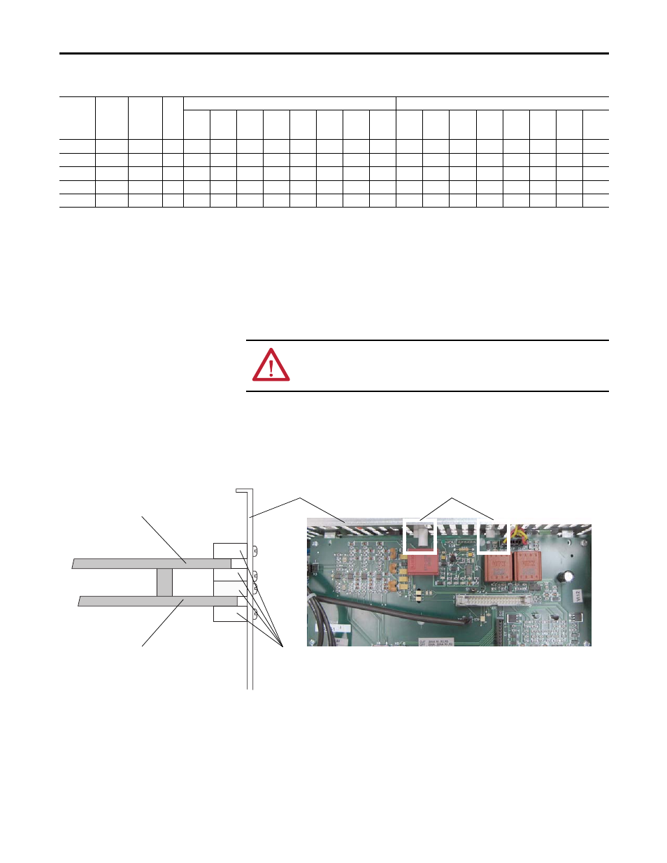
1. Install the new Pulse Transformer board and existing Switching Power
Supply board in reverse order of removal.
2. Replace the cables connected to connector X3, X4, XP and XR on the
Pulse Transformer board and the gate lead cables with the new cables
provided.
3. Verify that the four plastic board stabilizers mounted on the top air flow
plate are placed one on either side of each of the Pulse Transformer and
Switching Power Supply boards.
Drive
Current
Rating
Code
DC
Amps
AC Line
Amps
HP
DIP Switch S3
DIP Switch S4
S3-1
S3-2
S3-3
S3-4
S3-5
S3-6
S3-7
S3-8
S4-1
S4-2
S4-3
S4-4
S4-5
S4-6
S4-7
S4-8
67
67
55.1
50
ON
ON
ON
ON
101
101
82.7
75
ON
ON
ON
ON
135
135
110.3
100
ON
ON
ON
ON
270
270
220.6
200
ON
ON
ON
ON
405
405
330.9
300
ON
ON
ON
ON
ATTENTION: Each gate lead cable must be connected to the exact connector
from which it was removed on the Pulse Transformer circuit board or damage to
the drive may occur.
One plastic stabilizer should be on either side of each board
Air flow plate
Plastic
stabilizers
Top view of Pulse Transformer board
Side cut-away view
Pulse Transformer board
Switching Power Supply board